 Loading...
Do you have a question about the Sony ICF-SW7600GR - Portable Radio and is the answer not in the manual?
| Manufacturer | Sony |
|---|---|
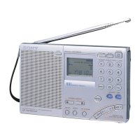
| Model | ICF-SW7600GR |
| Display | LCD |
| Type | Portable Radio |
| Power Source | 4 AA batteries or AC adapter |
| Features | SSB reception |
| Tuning Modes | Manual, Scan, Preset |
| Antenna | Telescopic antenna for FM/SW, built-in ferrite bar antenna for LW/MW |
| Speaker | Built-in |
| Headphone Jack | 3.5 mm |
| Tuning Steps | FM: 0.05 MHz, SW: 1 kHz, MW: 9/10 kHz, LW: 9 kHz |
| Weight | 617 g (1 lb 6 oz) including batteries |