1616
ICF-SW7600GR
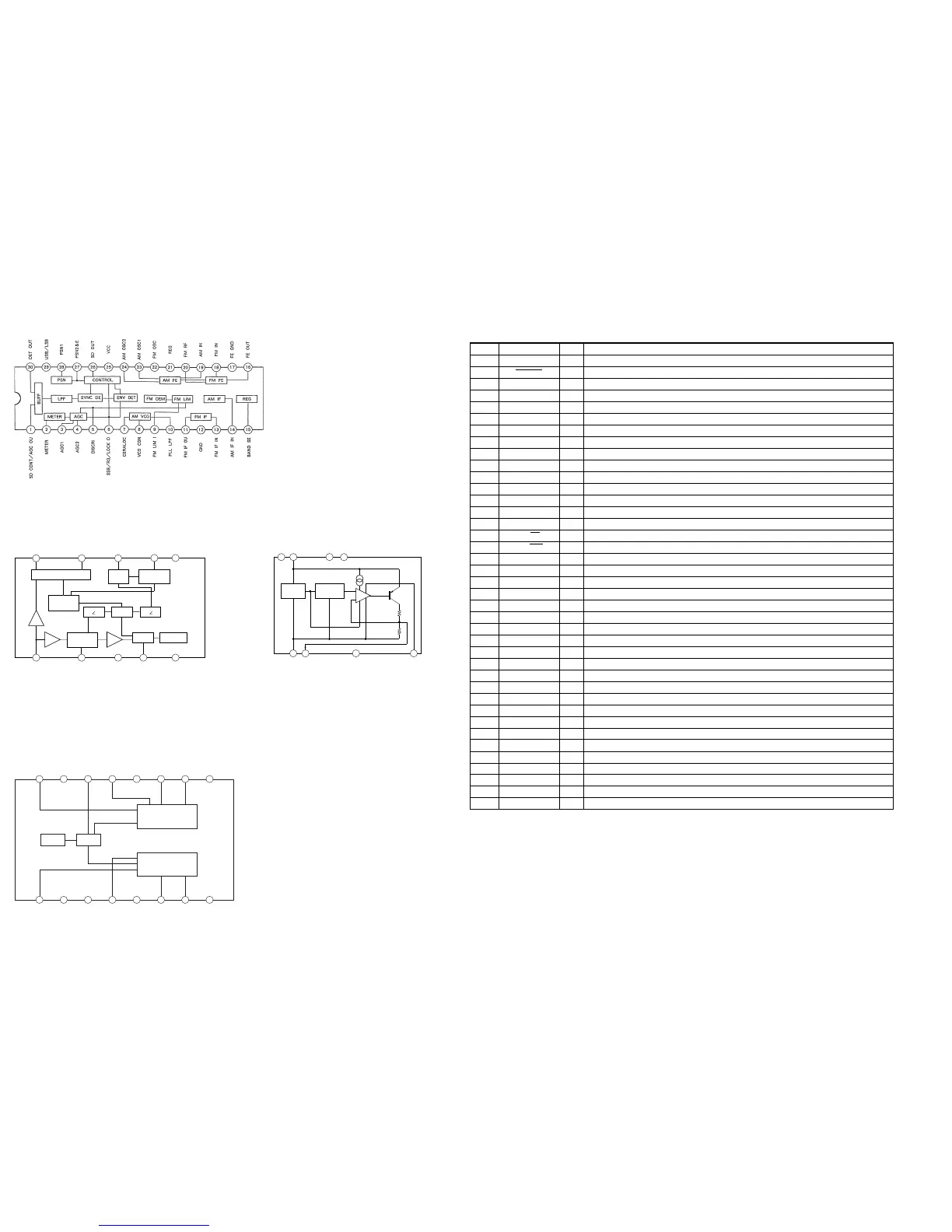
• IC BLOCK DIAGRAMS
IC201 CXA1376AS
IC202 LA3335M
IC203 CXA1522P
IC204 LA5003M
VOLREG
IN2
NC
NC
NF2
GND2
P-GND2
OUT
RIPPLE
IN1
REG
VOL
NF1
GND1
P-GND1
OUT1
VCC
PRE+POWER 1
PRE+POWER 2
1 2 3 4 5 6 7 8
16 15 14 13 12 11 10 9
FF 0º
1
234
5
6
7
8
910
FF 1/2FF 90º
V.C.O VCO STOP
SYNC
DET
STEREO
SWITCH
PHASE
COMPALATE
LAMP
TRIGGER
DECODER
IN
FILTER
VCC
VCO
NC
GND
STLED
M/ST
L
R
1
2
3
4
5
6
7
8
ERROR
AMP
GND
OUT
NC
C
NC
IN
NC
NC
REFERENCE
REGULATOR
TRIGGER
CIRCUIT
4-8. IC PIN FUNCTION DESCRIPTION
• IC302 µPD17073GB-564-1A7 (DIGITAL TUNING SYSTEM CONTROL)
Pin No.
1
2
3
4
5
6
7
8
9
10
11
12
13
14
15
16
17
18
19
20
21
22
23
24
25
26
27
28
29
30
31 - 34
35 - 49
50
51
52
53
54
55
56
I/O
O
O
O
O
O
O
O
O
O
I
I
I
I
I
O
O
O
–
O
I
I
O
–
O
I
O
O
–
–
O
O
O
I
I
O
I
I
O
I/O
Pin Name
LIGHT
MUTING
KS6
KS5
KS4
KS3
KS2
KS1
KS0
KR3
KR2
KR1
KR0
HOLD
POWER
AM/FM
BAR/ROD
GND
EO
VCOL
VCOH
REG PLL
VDD
XOUT
XIN
REG OSC
REG LCD0
CAP LCD0
CAP LCD1
REG LCD1
COM0 - 3
LCD0 - 14
CE
VDET
BEEP
SD
METER
SCK
SI/SO
Description
Light control signal output
Muting signal output
Key source signal output
Key source signal output
Key source signal output
Key source signal output
Key source signal output
Key source signal output
Key source signal output
Key return signal input
Key return signal input
Key return signal input
Key return signal input
Key input protect switch signal input
Radio power control signal output
AM/FM select signal output
Bar/Rod antenna select signal output
Ground
Error signal output
AM VCO (local oscillation) frequency input
FM VCO (local oscillation) frequency input
Output of PLL voltage regulator
Power supply (+3V)
Pin for connecting crystal resonator for system clock
Pin for connecting crystal resonator for system clock
Output of voltage regulator for oscillation circuit
LCD drive voltage output
Pin for capacitor connection for LCD drive voltage
Pin for capacitor connection for LCD drive voltage
LCD drive voltage output
LCD common signal output
LCD segment signal output
Chip select enable input
Low voltage detect signal input
BEEP signal output
Signal detector signal input
Reception level signal input
Serial clock output for EEPROM
Serial data input or output for EEPROM

 Loading...