— 5 —
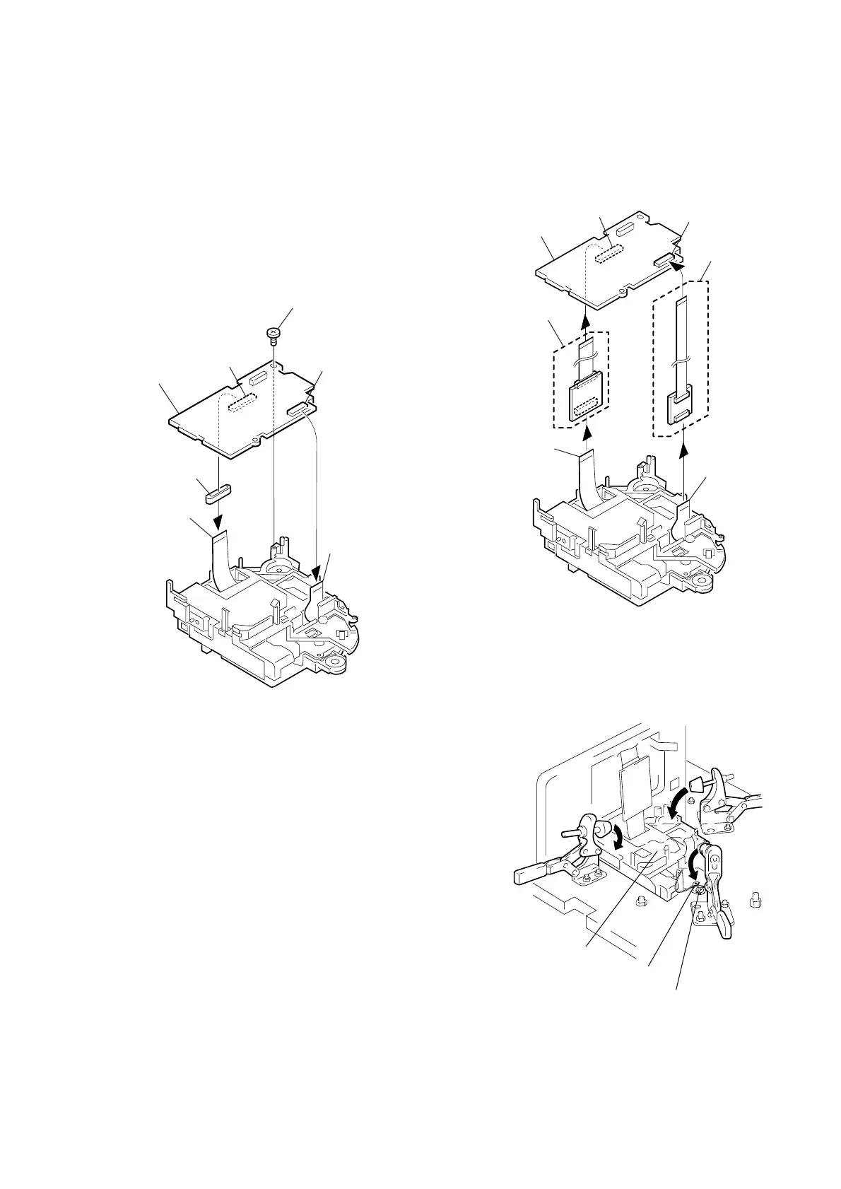
3. Attaching the MD to the BU
adjustment jig
Note: Remove the power supply from the BU adjustment jig.
1) Before attaching the MD (Mechanism deck of the DDX-G2100)
to the BU adjustment jig, perform the following work on the
MD as the preparation.
1 Remove the screw fixing the MD-083 board. (Fig.3-1)
2 Remove the flexible board (CN002 on the MD-083 board) of the
spindle motor.
3 Open the MD-083 board.
4 Remove the flexible board (CN001 on the MD-083 board) of the
OP (Optical device).
5 Connect CN002 on the MD-083 board and the flexible board of
the spindle motor using the 18 pin extension cable (Note).
(Fig.3-2)
Note: Supplied with the BU adjustment jig. (Or J-6082-374-A)
6 Connect CN001 on the MD-083 board and the 32 pin flexible board
of the OP using the extension cable (Note).
Note: Supplied with the BU adjustment jig.
Fig.3-1
Fig.3-2
2) Turn the BU adjustment jig upside down.
3) Install the BU assy in the BU adjustment jig, and fix it. At
same time, put the GND wire in the part of the damper, and fix
it. (Fig.3-3)
Fig.3-3
MD-083
1 Screw
CN002
CN001
2 Flexible board
of the spindle moto
4 Flexible board
of the OP
Ferrite core
3 MD-083 board
MD-083
CN002
CN001
Flexible board
of the spindle motor
Flexible board
of the OP
6 32 pin
extension cable
5 18 pin
extension cabl
MD-083 board
Damper
GND wire
BU assy

 Loading...


