— 34 —
OUTLINE OF TROUBLESHOOTING THE DDX-G2100 AND REMEDIAL MEASURE IN CASE OF FAILURE
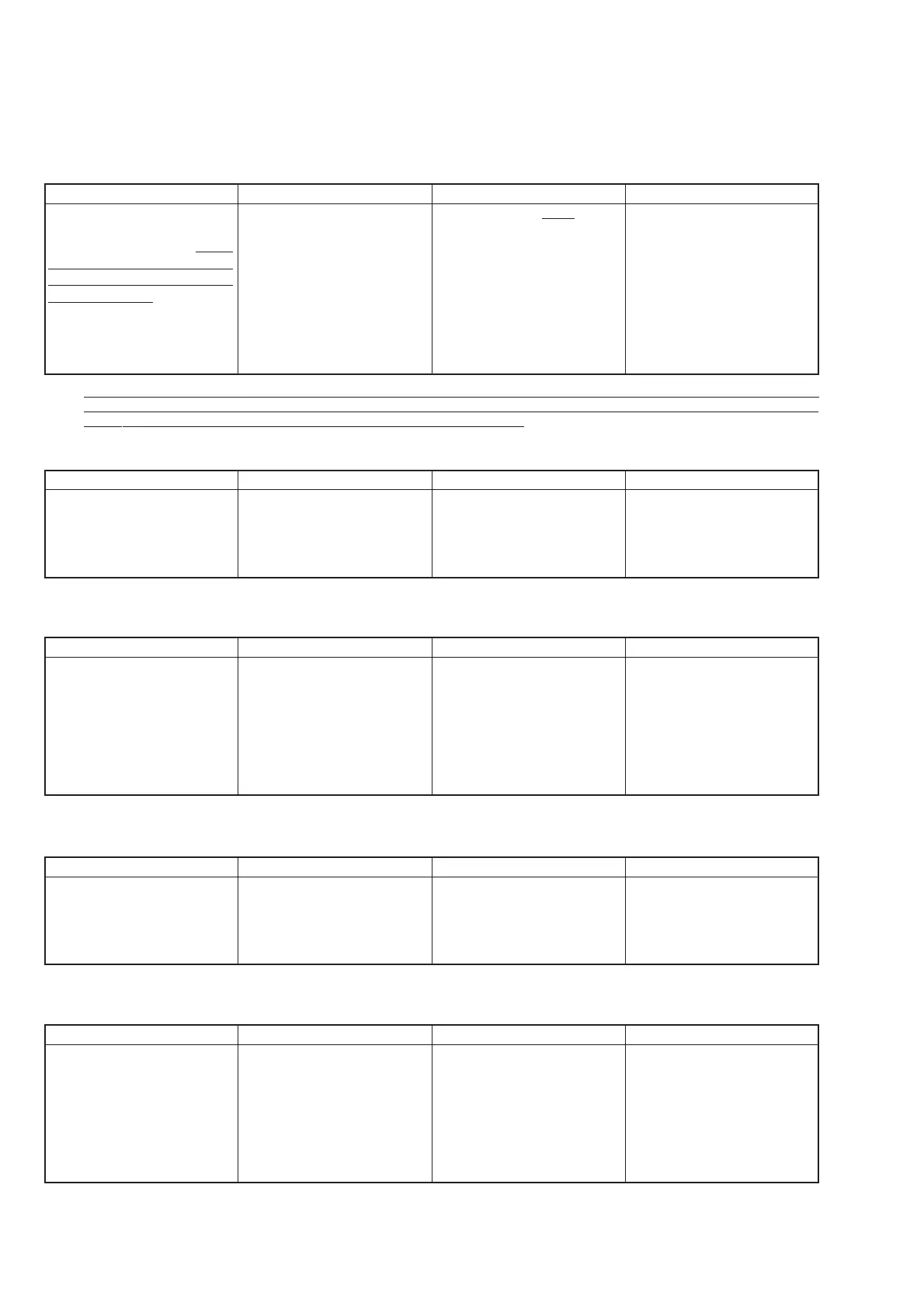
1. Laser Power Adjust
1-1. EEPROM preset t NG
1-3. Read Power t NG
1-4. LD Initial Check t NG
1-5. Front Monitor Gain t NG
Note: This item aims at the analysis of trouble using the electrical adjustment jig. The normal adjustment can be started with this item by the minimum
initialization of the EEPROM as described above. If the adjustment cannot be performed even though this item is performed, use the “EEPROM
Initialize” button below to completely initialize the EEPROM and restart the adjustment.
1-2. Cover Switch Check t NG
Purpose
Prior to start all the adjustments,
check the communication be-
tween USB and ATAPI. At the
same time, the minimum portion
of the EEPROM is initialized to
enable adjustment. See note.
Trouble Symptom
The disk check (seek sound) does
not start even though a disc is in-
serted in the repair jig. USB is not
recognized.
Communication doesn’t go well
because resetting of the micro-
computer isn’t sufficient.
Cause
Communication is faulty.
Abnormality of the machine is not
suspected.
Communication becomes faulty
when, for example, a flexible
printed wiring board is inserted
while the main power is turned on.
The microprocessor enter the boot
mode that makes communication
impossible.
Repair
Do it again from the start of the
jig and the PC.
Purpose
Checks operation of the lid open
detection circuit.
Trouble Symptom
Cover Open is detected: NG
Cause
The microprocessor detects the
High signal regardless of the
“open” detection information
from the jig. IC422 is defective or
input of IC002 is shorted.
Repair
Check IC422 and IC002.
Purpose
Read power adjustment
Trouble Symptom
(1) The laser power meter does
not show any value even if the
+ key is pressed.
(2) The laser power meter indica-
tor does not increase to the
specified value even if the +
key is pressed.
Cause
The laser OFF signal is output all
the time due to defective laser
power cutoff circuit IC002.
Output of the laser power is low
due to life or faulty of the laser
power diode in the OP unit.
Repair
Check IC002.
Replace the OP unit.
Purpose
Initialization for setting the read/
write laser power value and con-
firmation of control voltage.
Trouble Symptom
The NG indication appears.
Cause
Because output of the front moni-
tor of the OP unit is low, the write
laser power setup voltage WVDC
has increased exceeding the speci-
fied value.
Repair
Replace the OP unit.
Purpose
Set the maximum write power.
Match the relationship between
the maximum write power setup,
the control voltage and the gener-
ated power. Obtain the relation
between the laser power change
against VWDC1 and reject the de-
teriorated laser unit.
Trouble Symptom
When command is entered as
specified on the screen, the mea-
surement value is input. The NG
indication appears.
Cause
Output of the optical laser is low
due to deterioration of the laser
unit (OP unit). Either the laser
output does not correspond to the
change of the VWDC voltage or
the laser unit (OP unit) is defec-
tive.
Repair
Replace the OP unit.

 Loading...


