26
Setting Tally
Preparation
c In the list on the right, select the signal you want to
assign.
In this example, select “CAM1”.
d Press [Set].
4
Repeat steps 2 and 3 as required to assign other signals
to other subscreens.
Setting Multi Viewer Tally Output
To display the tally on the multi viewer screen, you must
set the same tally type as specified in step 2 of “Setting
Serial Tally” (1 p. 26).
1
Display the menu.
a Open the Engineering Setup >Panel >Operation
menu (7326).
b Press [Button Tally].
The Button Tally menu (7326.9) appears.
2
Set the tally type.
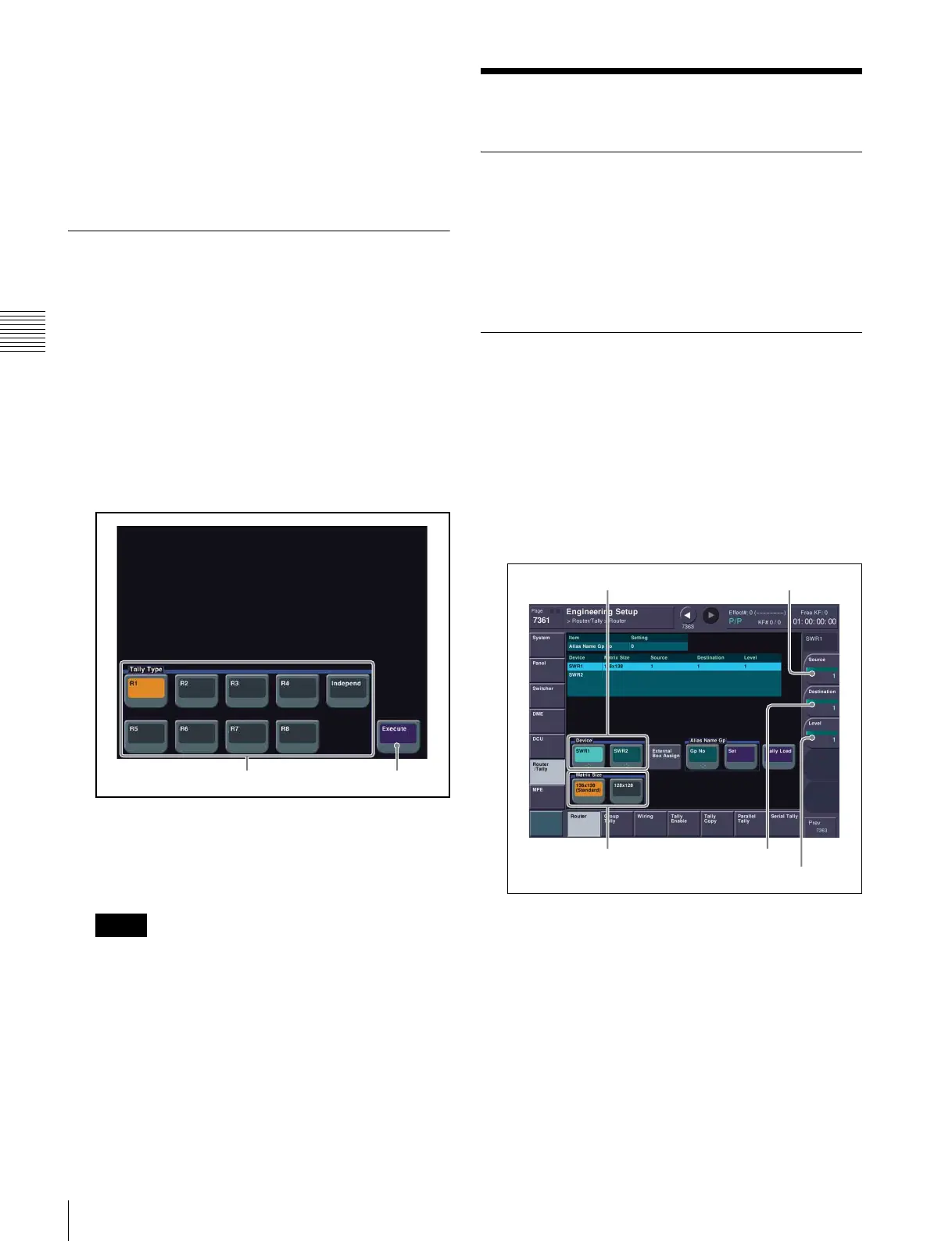
Button Tally menu
a In the <Tally Type> group, select the tally type.
In this example, select [R1].
b Press [Execute].
To display a tally on the multi viewer screen, select the
tally type from [R1] to [R8]. If you set [Independ], the
tally is not shown.
When any of the red tally types [R1] to [R8] is
selected, the corresponding green tally is
automatically set. For example, when [R1] is selected,
[G1] is automatically set as green tally. Note that you
must set the tally type [G1] in step 2 of “Setting Serial
Tally” (1 p. 26) beforehand.
Setting Tally
Setting Parallel Tally
The red tallies for PRIMARY INPUTS 1 to 48 are
assigned to the TALLY connector on the switcher
processor by default.
For details about changing the assignment settings, refer
to the User’s Guide.
Setting Serial Tally
Set the red tally of the program output (P/P PGM1) and the
green tally of the preview output (P/P PVW) to be output
from the SERIAL TALLY connector of the switcher
processor.
This section describes the procedure when “P/P PGM1” is
assigned to the OUTPUTS 1 connector and “P/P PVW” is
assigned to the OUTPUTS 2 connector.
1
Set the position of the MVS system in S-Bus space.
Router menu
a Open the Engineering Setup >Router/Tally
>Router menu (7361).
b In the <Device> group, select the target device.
In this example, select [SWR1].
c In the <Matrix Size> group, select the matrix size.
In this example, select [136x138 (Standard)].
d Set each of the [Source], [Destination], and [Level]
parameters to “1”.
Notes
Tally Type Execute
Matrix Size Destination
Source
Level
Device