6
Names of Parts
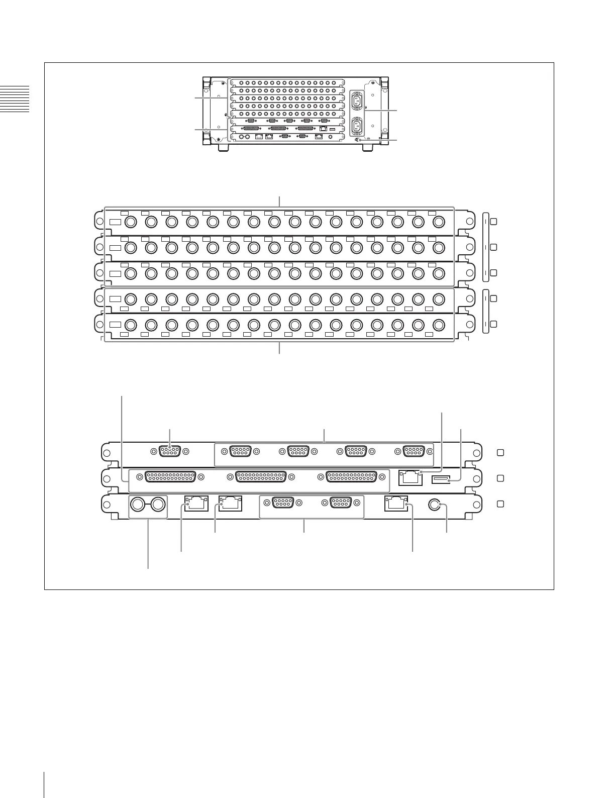
Overview
Rear panel: MVS-6530
a - AC IN (AC power input) A and B connectors
(3-pin)
Connect to 100 V to 240 V AC power supply with the
optional AC power cords.
The unit is equipped with two power supplies. When A or
B power supply is connected, unit operation can proceed.
b U (signal ground) terminal
Connect to the system ground.
c PRIMARY INPUTS
1 to 32 connectors (BNC-type)
1)
: MVS-6520
1 to 48 connectors (BNC-type)
1)
: MVS-6530
These connectors allow you to input up to 32 or up to 48
serial digital video signals to the MVS-6520 or MVS-6530
system, respectively.
1
IN
2 3 4 5 6 7 8 9 10 11 12 13 14 15 16
1
IN
2 3 4 5 6 7 8 9 10 11 12 13 14 15 16
1
IN
2 3 4 5 6 7 8 9 10 11 12 13 14 15 16
1
OUT
2 3 4 5 6 7 8 9 10 11 12 13 14 15 16
1
OUT
2 3 4 5 6 7 8 9 10 11 12 13 14 15 16
1
16
17
32
33
48
1
2
3
4
5
1
16
17
32
6
7
8
SERIAL TALLY REMOTE 4 REMOTE 3 REMOTE 2 REMOTE 1
TALLY/GPI IN13-18 OUT33-48 TALLY/GPI IN7-12 OUT17-32 TALLY/GPI IN1-6 OUT1-16 UTIL
(
FM
)
FM DEVICE
REF IN UTIL
(
SW
)
MVS REMOTE S2 REMOTE S1 UTIL
(
SCU
)
S-BUS
Slots 6 to 8
Slots 1 to 5
Slots 1 to 5
Slots 6 to 8
a -AC IN A and B connectors
b U terminal
g REMOTE 1 to 4 connectors i FM DEVICE connector
j S-BUS connector
h UTIL (FM) connector
d OUTPUTS 1 to 32 connectors
o REF INPUT connectors
n UTIL (SW) connector
m MVS connector l REMOTE S1 and S2
connectors
k UTIL (SCU) connector
c PRIMARY INPUTS 1 to 48 connectors
f SERIAL TALLY connector
e TALLY/GPI IN 1 to 18 and TALLY/
GPI OUT 1 to 48 connectors

 Loading...


