SA-WCT800
3
SECTION 1
SERVICING NOTES
UNLEADED SOLDER
Boards requiring use of unleaded solder are printed with the lead-
free mark (LF) indicating the solder contains no lead.
(Caution: Some printed circuit boards may not come printed with
the lead free mark due to their particular size)
: LEAD FREE MARK
Unleaded solder has the following characteristics.
• Unleaded solder melts at a temperature about 40 °C higher
than ordinary solder.
Ordinary soldering irons can be used but the iron tip has to be
applied to the solder joint for a slightly longer time.
Soldering irons using a temperature regulator should be set to
about 350 °C.
Caution: The printed pattern (copper foil) may peel away if
the heated tip is applied for too long, so be careful!
• Strong viscosity
Unleaded solder is more viscous (sticky, less prone to fl ow)
than ordinary solder so use caution not to let solder bridges
occur such as on IC pins, etc.
• Usable with ordinary solder
It is best to use only unleaded solder but unleaded solder may
also be added to ordinary solder.
ADVANCE PREPARATION WHEN CONFIRMING OP-
ERATION
All of the units included in the HT-CT800 (SA-WCT800/SA-
CT800/Remote control) are required to confi rming operation of
SA-WCT800. Check in advance that you have all of the units.
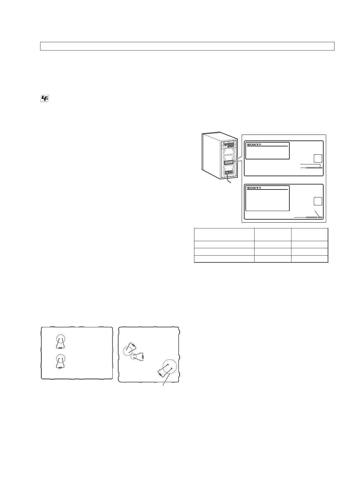
CAPACITOR ELECTRICAL DISCHARGE PROCESSING
Before checking the operation of the boards for the electric shock
prevention, perform the discharge processing by connecting the
resistor at both ends of capacitor with referring to the fi gure below.
Note 1: When the connector that connects the SUB-MAIN board to the
SUB-POWER board is disconnected before discharging, com-
pletely fi nish discharging both boards, and then reconnect the con-
nector. If discharging is not complete, sparking may occur when
connecting the connector and cause a blown fuse.
Note 2: Be sure to discharge using a resistor of 800 or higher.
– SUB-POWER Board
(Conductor Side) –
C967
C970
C914 (US, CND)
C915 (AEP, UK)
C7234
C7233
– SUB-MAIN Board
(Conductor Side) –
800 :/2 W
800 :/2 W
800 :/2 W
800 :/2 W
800 :/2 W
NOTE OF PERFORMING THE OPERATION CHECK IN
THE STATE THAT HEAT SINK IS REMOVED
When performing the operation check in the state that this unit is
disassembled, it is possible to perform the operation check in the
state that heat sink is removed. However, don’t perform the opera-
tion check in the long time, and perform the operation check in the
volume state as low as possible.
The SERVICING NOTES contains important information for servicing. Be sure to read this section before repairing the unit.
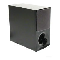
THE POWER INDICATOR FLASHES IN RED
q If the power indicator on the
subwoofer flashes in red, press Æ
(power) of the subwoofer to turn off
the power and check whether the
ventilation holes of the subwoofer is
blocked or not.
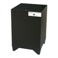
MODEL IDENTIFICATION
Distinguish by Part No. and Destination code of the model number
label on the rear side of the main unit.
US, CND
AEP, UK
– Rear view –
MODEL NUMBER LABEL
Destination code
Part No.
Destination
code
Part No.
Destination Part No.
Destination
code
US, CND models
4-684-829-0[]
(UC2)
AEP model
4-684-831-0[]
(CEL)
UK model
4-690-910-0[]
(CEK)
DESTINATION ABBREVIATIONS
The following abbreviations for model destinations are used in this
service manual.
• Abbreviations
AEP : European (Except for Ireland, UK), Eastern Europe area,
CIS area (Moldova) and Middle East area (Jordan) models
CND : Canadian and Latin America area (Puerto Rico) models
UK : UK and Ireland models
 Loading...