SA-WCT800
6
SECTION 2
DISASSEMBLY
• This set can be disassembled in the order shown below.
2-1. DISASSEMBLY FLOW
SET
2-4. POWER CORD (AC1)
(Page 8)
2-5. SUB-POWER BOARD
(Page 9)
2-6. RF MODULATOR (RF1)
(Page 10)
2-7. SUB-KEY BOARD, BUTTON (POWER-CZ2)
(Page 10)
2-2. AMP BLOCK
(Page 6)
2-3. SUB-MAIN BOARD
(Page 7)
2-9. LOUDSPEAKER (SP1)
(Page 12)
2-8. SUB LED BOARD, FRONT PANEL ASSY
(Page 11)
JIG
When disassembling the unit, use the following
jig for speaker removal.
Part No. Description
J-2501-238-A JIG FOR SPEAKER REMOVAL
Note: Follow the disassembly procedure in the numerical order given.
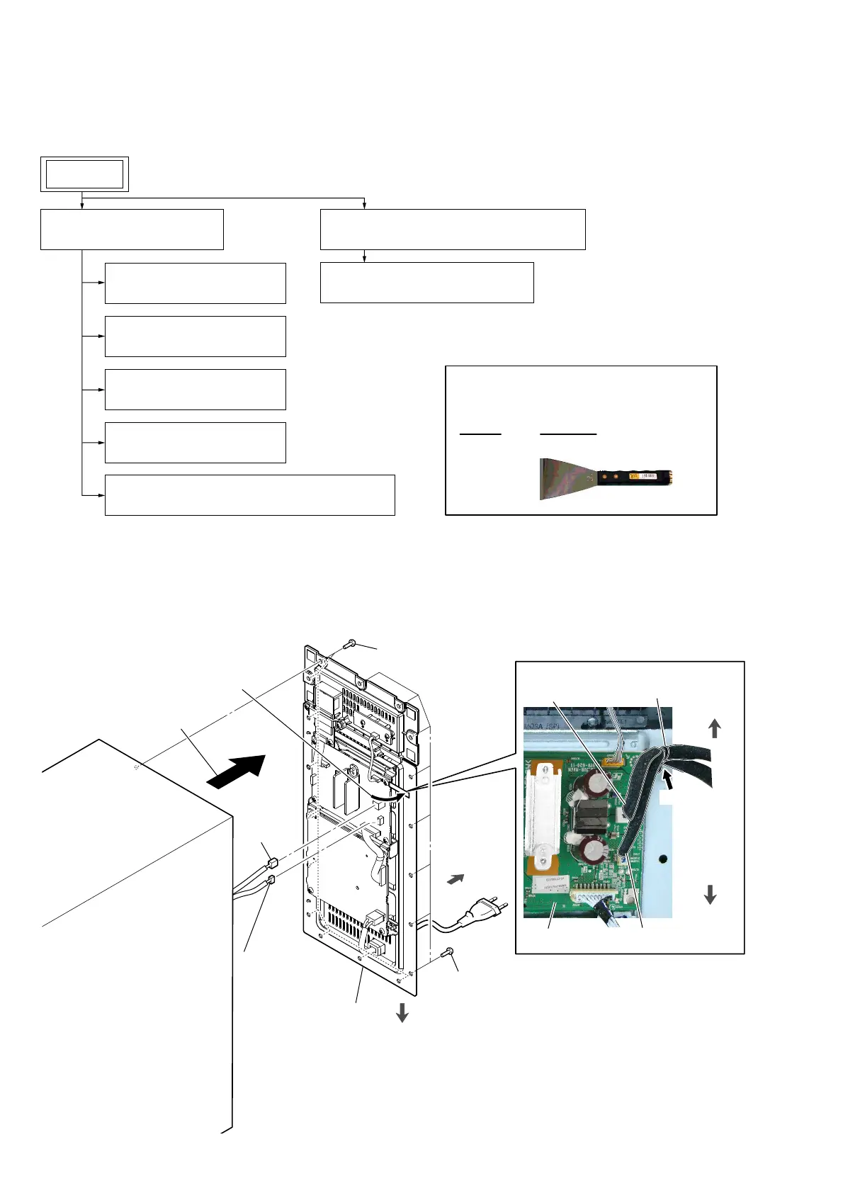
2-2. AMP BLOCK
:LUHVHWWLQJ
6 AMP block
1 eight tapping screws
(3.5 u 16)
1 ten tapping screws
(3.5 u 16)
2 Remove the AMP block in
the direction of the arrow.
3 Remove the two cables
from the wiring stopper.
rear side
wiring stopper
top side
bottom side
bottom side
5 speaker
cable
connector
(CN7202)
4 SUB LED board
cable connector
(CN7405)
Push.
SUB-MAIN board
speaker cable
SUB LED board cable
 Loading...