10 (GB)
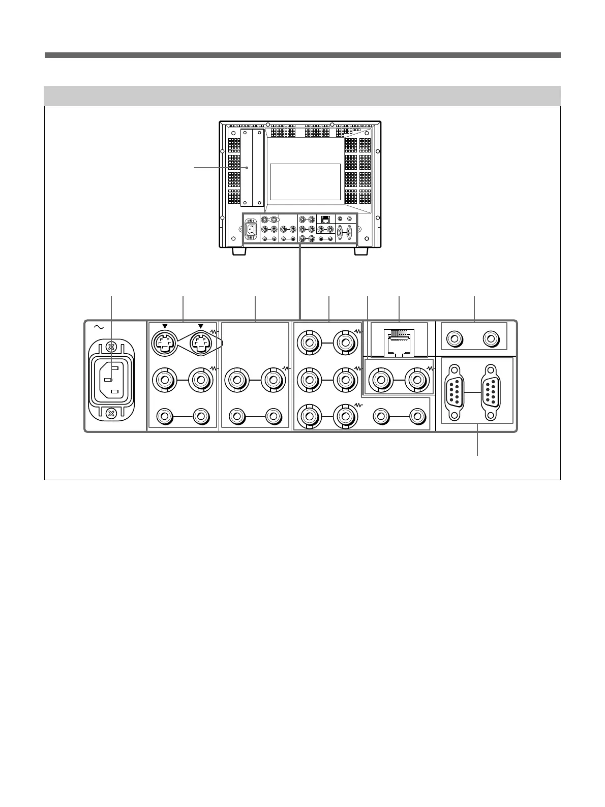
Location and Function of Parts and Controls
1 Option slot
You can insert an option board into this option slot. To
use this slot, remove the slot cover by removing the
screws.
You can install only one option board. For details on how to
install a board, refer to the Operating Instructions supplied
with the option board.
2 AC IN socket
Connect the supplied AC power cord to this socket and
to a wall outlet.
3 LINE A connectors
Line input connectors for the Y/C separate input/
output of a VCR, composite video and audio signals
and their loop-through output connectors.
To monitor the input signal through these connectors,
press the LINE A select button on the front panel.
If you connect the Y/C input and video input
simultaneously, the Y/C input is selected first.
Y/C IN (4-pin mini-DIN)
Connect to the Y/C separate output of a VCR,
video camera or other video equipment.
Y/C OUT (4-pin mini-DIN)
Loop-through output of the Y/C IN connector.
Connect to the Y/C separate input of a VCR or
another monitor.
When the cable is connected to this connector, the
75-ohm termination of the input is automatically
released, and the signal input to the Y/C IN
connector is output from this connector.
VIDEO IN (BNC)
Connect to the video output of video equipment,
such as a VCR or a color video camera.
For a loop-through connection, connect to the video
output of another monitor.
AC IN LINE A LINE B
VIDEO
AUDIO
IN OUT
IN OUT
VIDEO
AUDIO AUDIO
PARALLEL REMOTE
SERIAL REMOTE
OPTION AUDIO INPUT
RGB/COMPONENT
IN OUT
IN OUT
B/P
B
G/Y
R/P
R
IN OUT
IN OUT IN OUT
EXT
SYNC
IN OUT
IN OUT
12
1
2
34
567 8
9
Rear Panel
 Loading...