6.4 Power supply and power selection
6.4.1 External power supply input
It is possible to configure the STM32U5 Nucleo-144 board to use any of the following power sources:
• 5V_STLK from STLINK-V3E USB connector (CN1)
• VIN (7 to 12 V) from ARDUINO
®
-included Zio connector (CN8) or ST morpho connector (CN11) with 5 V
adaptation from LDO (U11)
• 5V_EXT from ST morpho connector (CN11)
• 5V_USB_C from USB Type-C
®
connector (CN15)
• 5V_CHGR from STLINK-V3E USB connector (CN1)
•
3V3 from ARDUINO
®
-included Zio connector (CN8) or ST morpho connector (CN11)
If VIN, 5V_EXT, or 3V3 is used to power the STM32U5 Nucleo-144 board, this power source must comply
with the standard EN‑60950‑1: 2006+A11/2009 and must be safety extra‑low voltage (SELV) with limited power
capability.
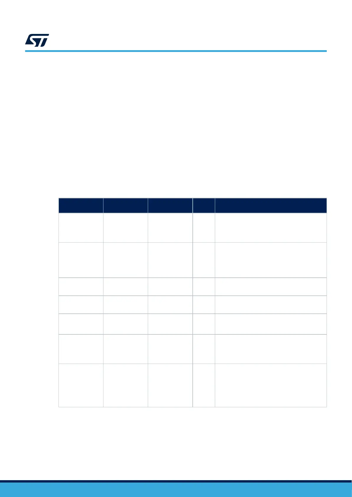
The power supply capabilities are summarized in Table 8.
Table 8. Power sources capability
Input Power name Connector pins Voltage range
Max.
current
Limitation
5V_STLK
CN1 pin 1
JP6 [1-2]
4.75 to 5.5 V 500 mA
The maximum current depends on the presence or
absence of USB enumeration:
• 100 mA without enumeration
• 500 mA with enumeration OK
VIN / 5V_VIN
CN8 pin 15
CN11 pin 24
JP6 [3-4]
7 to 12 V 800 mA
From 7 to 12 V only and input current capability is
linked to input voltage:
• 800 mA input current when VIN = 7 V
• 450 mA input current when 7 V < VIN < 9 V
• 250 mA input current when 9 V < VIN < 12 V
5V_EXT
CN11 pin 6
JP6 [5-6]
4.75 to 5.5 V 500 mA
The maximum current depends on the power
source.
5V_USB_C
CN15
JP6 [7-8]
4.75 to 5.5 V 1 A
The maximum current depends on the USB host
used to power the Nucleo.
5V_CHGR
CN1 pin 1
JP6 [9-10]
4.75 to 5.5 V 500 mA
The maximum current depends on the USB wall
charger used to power the Nucleo. There is no
USB enumeration.
3V3
CN8 pin 7
CN11 pin 16
JP5 pin 2
3.0 to 3.6 V -
The maximum current depends on the 3V3 source.
The 3V3 can be used when the STLINK-V3E part
of the PCB is not used. SB1 must be OFF to
protect LDO (U10).
VDD JP4 pin 2 1.71 to 3.6 V
It is possible to power only the MCU power
supplies pins by applying a voltage source on JP4
pin 2. In this case, only the MCU is powered.
External functions like debugging, LED, or the
expansion connector are not powered. This option
can be used for the MCU power consumption
measurement.
UM2861
Power supply and power selection
UM2861 - Rev 5
page 16/49
 Loading...