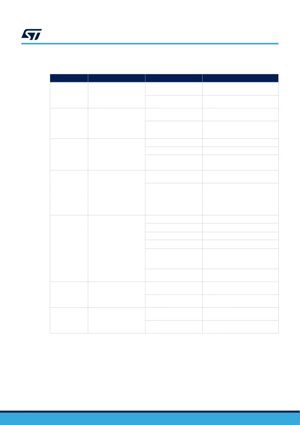
Table 5 explains the other jumper settings and configurations.
Table 5. Jumper configuration
Jumper Definition
Setting
(1)
Comment
JP1 STLK_RST
ON
Use to reset the STLINK-V3E MCU
when an external debug probe is used.
OFF
STLINK-V3E is selected as the default
debugger.
JP2 T_NRST
ON
STLINK-V3E can reset the target
MCU.
OFF
STLINK-V3E cannot reset the target
MCU. Configuration to use when an
external debug probe is used.
JP4 VDD voltage selection
[1-2] VDD voltage selection is 3V3
[2-3] VDD voltage selection is 1V8
OFF
No internal VDD power supply
(External 3.3 or 1.8 V needed)
JP5
I
DD
measurement
ON
MCU is powered by the on‑board
power supplies.
OFF
Use an ammeter to measure the
VDD_MCU power consumption, or
connect a 3.3 or 1.8 V external
source on pin 2 (STLINK-PWR
tools with STM32CubeMonitor-Power or
ULPBench probe as exemple).
JP6
5V Power selection
(2)
[1-2] 5V source from STLINK-V3E
[3-4]
5V source from ARDUINO
®
VIN 7-12V
[5-6] 5V source from 5V_EXT
[7-8]
5V source from USB Type-C
®
[9-10]
5V source from USB_CHGR.
From STLINK-V3E USB connector
(CN1) without overcurrent protection.
OFF
NO 5V power source, configuration
when external 3V3 is used.
JP7 UCPD_DBCC1
OFF
UCPD_DBCC1 NOT connected to
GND
ON
UCPD_DBCC1 connected to GND (For
debug purpose)
JP8 UCPD_DBCC2
OFF
UCPD_DBCC2 NOT connected to
GND
ON
UCPD_DBCC2 connected to GND (For
debug purpose)
1. The default configuration is in bold.
2. This is recommended to have only one jumper configuration.
UM2861
Default board configuration
UM2861 - Rev 5
page 8/49
 Loading...