5 Quick start
The STM32G4 Nucleo-64 board is a low-cost and easy-to-use development kit, used to evaluate and start a
development quickly with an STM32G4 Series microcontroller in LQFP64 package. Before installing and using the
product, accept the Evaluation Product License Agreement from the www.st.com/epla webpage. For more
information on the STM32G4 Nucleo-64 and for demonstration software, visit the www.st.com/stm32nucleo
webpage.
5.1 Getting started
Follow the sequence below to configure the STM32G4 Nucleo-64 board and launch the demonstration application
(refer to Figure 4 for component location):
1. Check the jumper position on the board (refer to Table 4)
2. For the correct identification of the device interfaces from the host PC and before connecting the board,
install the Nucleo USB driver available on the www.st.com/stm32nucleo website
3. To power the board, connect the STM32G4 Nucleo-64 board to a PC with a USB cable (Type-A to Micro-B)
through the USB connector CN1 of the board
4. Then, green LED LD3 (5V_PWR) and red LED LD1 (COM) light up, green LED LD2 (USER) blinks
5. Press user button B1 (left blue USER button)
6. Observe how the blinking of the green LED LD2 changes according to the clicks on button B1
7. The software demonstration and the several software examples that allow users exercise Nucleo features,
are available on the www.st.com/stm32nucleo webpage
8. Develop your own application using the available examples
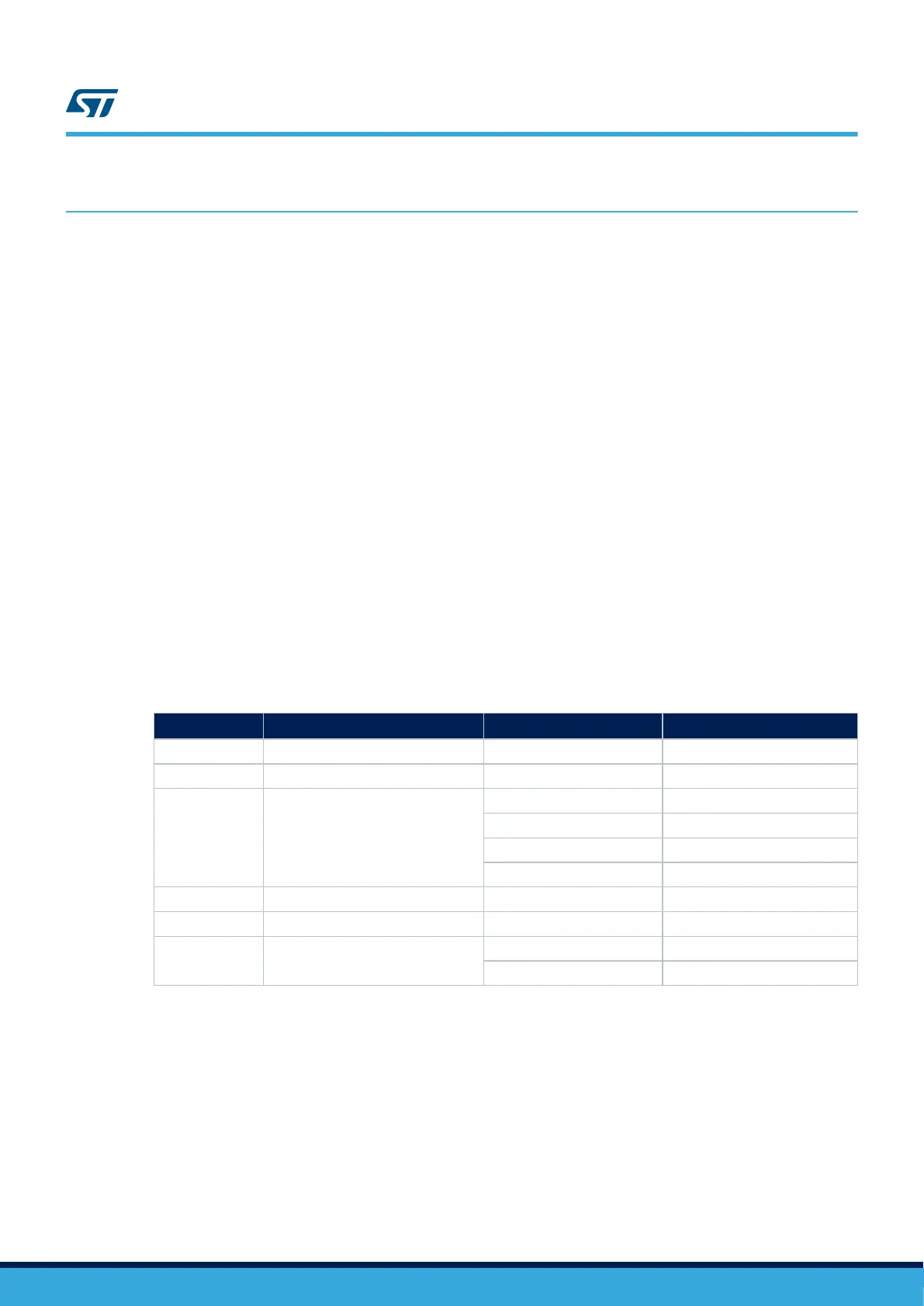
Table 4. Jumper configuration
Jumper
Definition
Position
(1)
Comment
(1)
JP1 NRST OFF STLINK-V3E reset
JP3 T_RST ON -
JP5 5 V power-source selection
ON [1-2] (Default) 5V_USB_STLK (from ST-LINK)
ON [3-4] (optional) 5V_VIN
ON [5-6] (optional) E5V
ON [7-8] (optional) 5V_USB_CHGR
JP6 IDD ON
JP7 BOOT0 OFF
JP8
VREF+ selection (VREF or VDD
voltage supply selection)
ON [1-2] (Default) VREF+ supplied with VREF
ON [2-3] (optional) VREF+ supplied with VDD
1. Default jumper state is shown in bold.
UM2505
Quick start
UM2505 - Rev 2
page 6/43

 Loading...


