UM2407 Rev 2 11/50
UM2407 Hardware layout and configuration
49
6 Hardware layout and configuration
The STM32H7 Nucleo-144 board is designed around the STM32H7 Series microcontrollers
in a 144-pin LQFP package.
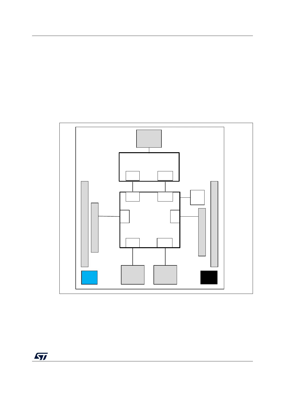
Figure 3 shows the connections between the STM32H7 and its peripherals (STLINK-V3E,
push-buttons, LEDs, USB, Ethernet, ST Zio connectors, and ST morpho headers).
Figure 4 and Figure 5 show the location of these features on the STM32H7 Nucleo-144
board.
The mechanical dimensions of the board are shown in Figure 6 and Figure 7.
Figure 3. Hardware block diagram
MSv51396V1
Embedded
STLINK-V3E
STM32
Microcontroller
ST morpho extension header
ST morpho extension header
IO
VCP
UART
B2
reset
button
B1
user
button
IO
Zio Connector
ST-LINK part
MCU part
LED1
LED2
LED3
Micro-AB
USB
connector
Zio Connector
RJ45
connector
Micro-B
USB
connector
SWD
SWD
VCP
UART
USB RMII

 Loading...


