UM2407 Rev 2 23/50
UM2407 Hardware layout and configuration
49
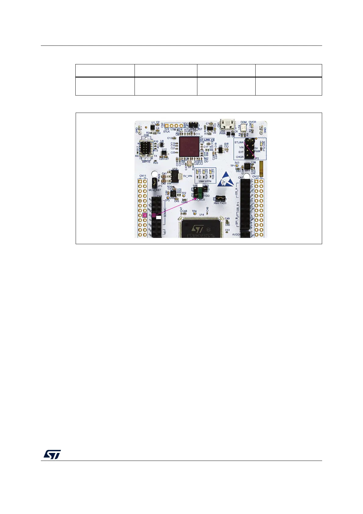
Figure 14. Power supply input from 3V3_EXT (3.3 V)
6.4.6 Debugging while using VIN or EXT as an external power supply
When powered by VIN or EXT, it is still possible to use the STLINK-V3E for programming or
debugging only, but it is mandatory to power the board first using VIN or EXT, then to
connect the USB cable to the PC. In this way, the enumeration succeeds, thanks to the
external power source.
The following power-sequence procedure must be respected:
1. Connect jumper JP2 between pin 5 and pin 6 for EXT or between pin 3 and pin 4 for
VIN
2. Connect the external power source to VIN or EXT
3. Power on the external power supply 7 V< VIN < 12 V to VIN, or 5 V for EXT
4. Check that the green LED LD5 is turned ON
5. Connect the PC to the USB connector CN1
If this order is not respected, the board may be powered by USB (U5V) first, then by VIN or
EXT as the following risks may be encountered:
1. If more than 300 mA current is needed by the board, the PC may be damaged or the
current supplied can be limited by the PC. As a consequence, the board is not powered
correctly.
2. 300 mA is requested at enumeration so there is a risk that the request is rejected and
the enumeration does not succeed if the PC cannot provide such current.
Consequently, the board is not power supplied (LED LD5 remains OFF).
Table 9. External power sources: 3V3_EXT (3.3 V)
Input power name Connector pins Voltage range Max current
3V3
CN8 pin 7
CN11 pin 16
3 V to 3.6 V 1.3 A
MSv61207V2
MSv61203V1
CN1
U2
3V3
NO DEBUG
3V3
NO JUMPER

 Loading...


