UM2407 Rev 2 27/50
UM2407 Hardware layout and configuration
49
Hardware connection required for USART bootloader:
The STM32H7x3 embeds a USART bootloader. To use the USART bootloader (USART1),
hardware modifications are required on the NUCLEO board. Flying wires have to be
connected between PD8/PD9 (USART3 available on SB19/SB12) and PB10/PB11
(USART1 available on CN15).
6.6.6 USB OTG FS
The STM32H7 Nucleo-144 board supports USB OTG FS communication via a USB Micro-
AB connector (CN13) and USB power switch (U18) connected to V
BUS
.
Warning: USB Micro-AB connector (CN13) cannot power the Nucleo-
144 board. To avoid damaging the STM32H7, it is mandatory
to power the Nucleo-144 before connecting a USB cable on
CN13. Otherwise, there is a risk of current injection on
STM32H7 I/Os.
A green LED LD8 lights in one of these cases:
• Power switch (U12) is ON and STM32H7 Nucleo-144 board works as a USB host
• V
BUS
is powered by another USB host when the STM32H7 Nucleo-144 board works as
a USB device.
The red LED LD7 lights if overcurrent occurs when +5 V is enabled on V
BUS
in USB host
mode.
Note: 1.It is recommended to power the Nucleo-144 board with an external power supply when
using USB OTG or host function.
2.SB76 must be ON when using USB OTG FS.
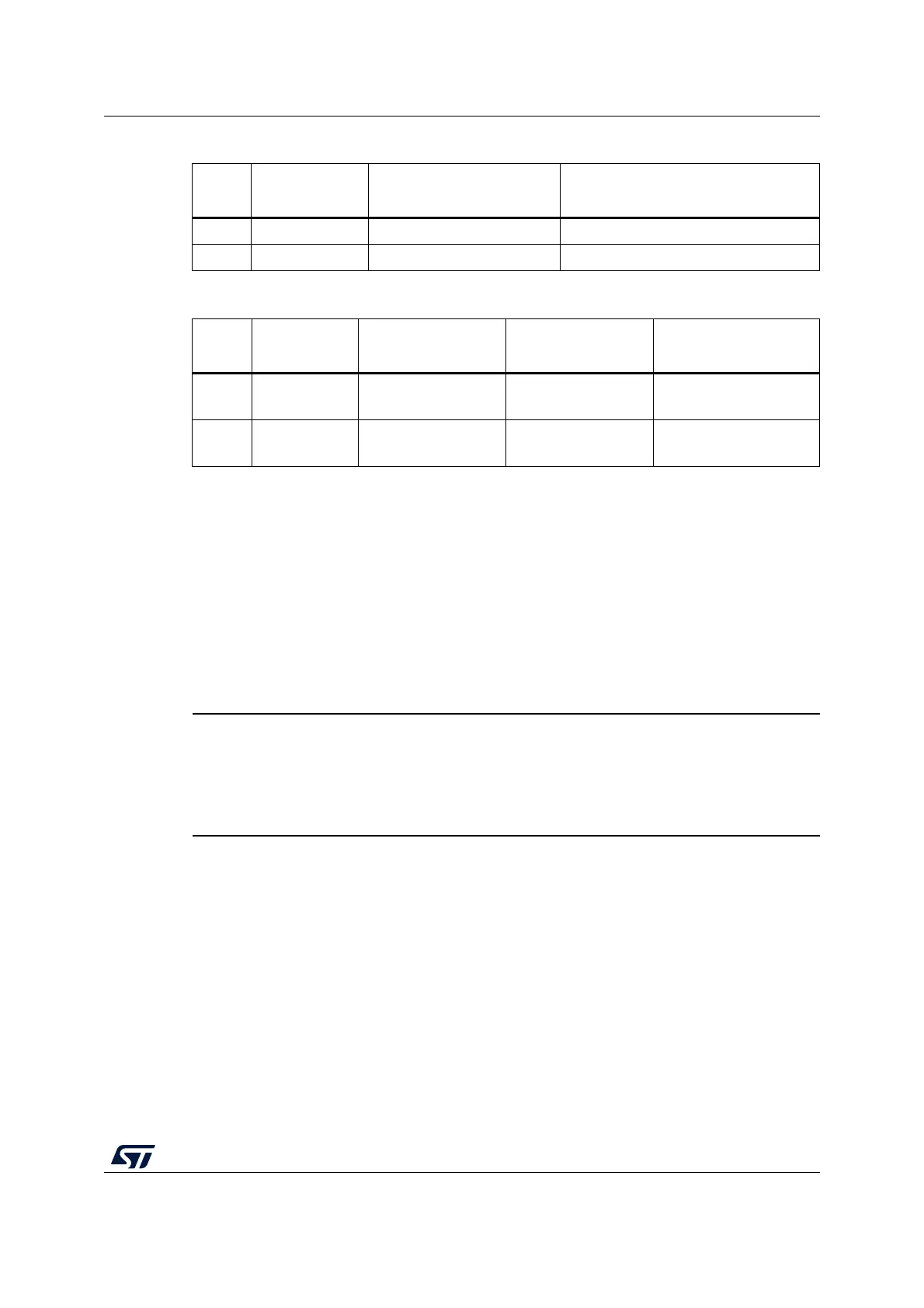
Table 10. USART3 connection
Pin
name
Function
Virtual COM port
(default configuration)
ST morpho connection
PD8 USART3 TX SB5 ON and SB7 OFF SB5 OFF and SB7 ON
PD9 USART3 RX SB6 ON and SB4 OFF SB6 OFF and SB4 ON
Table 11. LPUART1 connection
Pin
name
Function Virtual COM port
ARDUINO
®
D0 and
D1
ST morpho connection
PB6 LPUART1 TX
SB9 ON
SB8 and SB18 OFF
SB8 ON
SB9 and SB18 OFF
SB9 OFF and SB18 OFF
PB7 LPUART1 RX
SB34 ON
SB12 and SB68 OFF
SB68 ON
SB34 and SB66 OFF
SB12 OFF and SB34
OFF

 Loading...


