Edition Manual Chapter Page
2014-09-09 Workshop Manual, GGP Park 6 Control wires 9
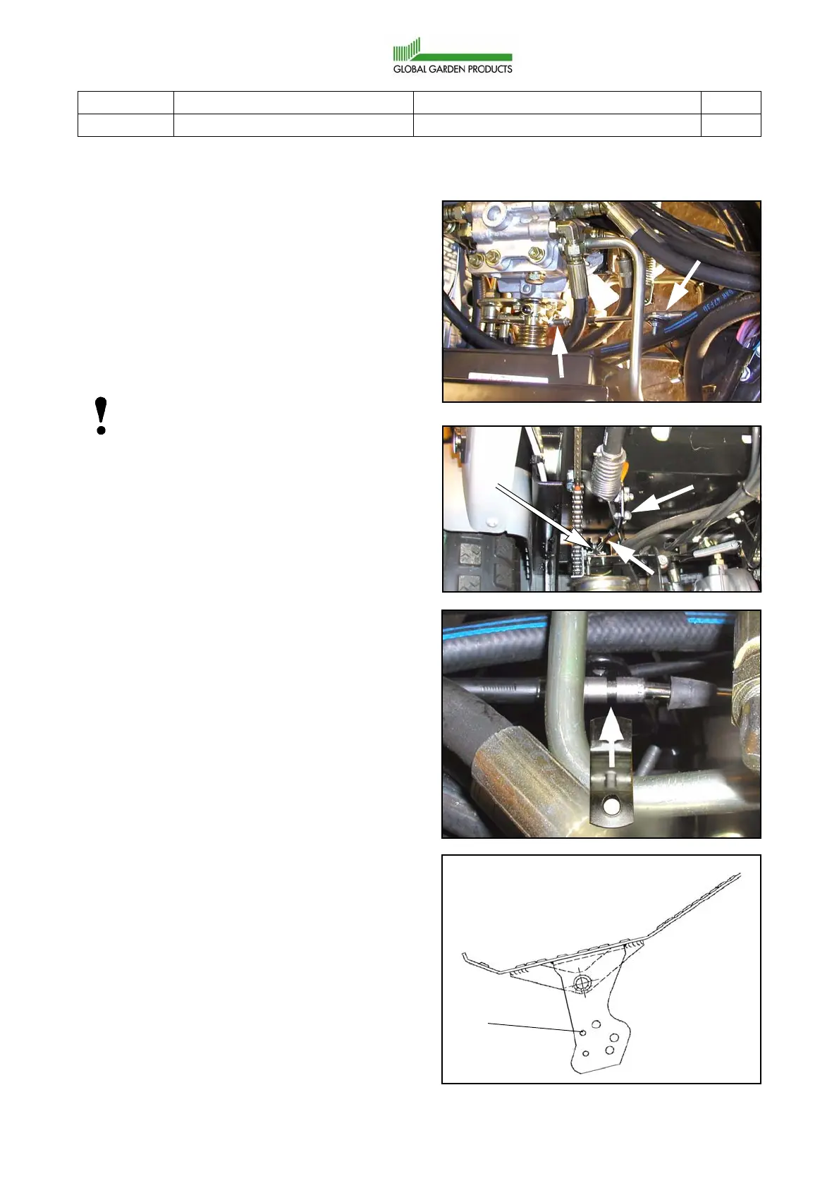
6.4 HST control wire
(4WD with external pump)
6.4.1 Replacement
1. Dismantle the control wire.
2. Fit the new wire in the same location as the
old one.
Note!
The longer support tube (C) shall be locat-
ed forwards.
3. Check the elbow links for damage or wear.
Replace with new links if necessary. Fit the
elbow links with their locking nuts at the
wire ends.
The links shall be screwed onto the wire
ends about 1 cm.
4. Fit the front and rear clamps (B). Make sure
that the dogs at the clamps fit in the
grooves in the wire cover. Both front and
rear. Se the figure.
5. Fit the elbow links (A) to the levers. See
“Elbow links” at page 3. The front elbow
link shall be fitted to the pedal in hole (D).
See the figure.
6. Assemble a new cable holder for the right
cable bundles.
7. Adjust the control wire as described below.
B
A
B
A
C
D
 Loading...