The machine is supplied with
some of the components disassembled and the
fuel tank empty.
Always wear strong work
gloves to handle the cutting devices. Mount
the components very carefully so as not to
impair the safety and efficiency of the ma-
chine. If in doubt, contact your dealer.
Unpacking and complet-
ing the assembly should be done on a flat and
stable surface, with enough space for moving
the machine and its packaging, always making
use of suitable equipment.
Disposal of the packaging should be done in ac-
cordance with the local regulations in force.
1. COMPLETING THE MACHINE
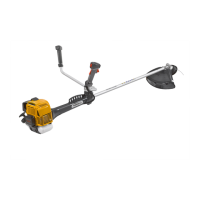
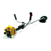
1a. “DUPLEX” models (Fig. 1)
– Unscrew the central knob (1) and remove the
cap (2).
– Insert the handlebar (3), making sure that the
controls are on the right.
– Set the handlebar in the most comfortable work-
ing position and lock it using the cap (2) and
knob (1).
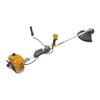
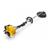
1b. “FLEX” models (Fig. 2)
– Position the upper part (2) with the front grip's
guard on the drive tube (1).
– Fasten the lower cap (4) inserting the pin (4a) in
the hole on the drive tube.
– Position the plate (3) under the back left screw.
– Fully tighten the screws (5).
Proceed as follows to connect the flexible tube to
the power unit:
– Insert the end of the shaft (8) into the hub (9) pro-
truding from the front handgrip, align the pin (10)
with the hole (11) in the drive tube flange and
fully screw in the sleeve (12).
– Insert the end of the shaft (13) into the hub (14)
protruding from the power unit, press the locking
IMPORTANT
button (15) and fully insert the flexible tube (16)
into its seating until the button (15) can be felt to
rise.
– Insert the register (17) of the throttle wire in the
support slot and connect the wire (18) to the
carburettor lever (19); then work the nuts (20) to
tighten the wire and block the register on the
support.
– Connect the two terminals of cables (21) and
(22) to the corresponding cables on the power
unit.
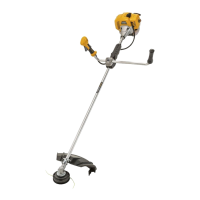
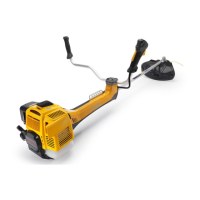
2. FITTING THE GUARD (Fig. 3)
Each cutting device is
provided with a specific guard. Never use
guards other than those indicated for each
cutting device.
Wear protective gloves
and fit the blade guard.
– Remove the cutting device (if fitted), as indi-
cated in paragraph 3.
– Fit the guard (1) to the angle transmission (2)
with two screws (3) inserted in the specific guard
holes (1) for each use, as indicated in para-
graphs 3.1 and 3.2.
3. REMOVING AND FITTING CUTTING
DEVICES AND PREPARING GUARDS
Use only original cutting
devices or ones homologated by the Manufac-
turer.
3.1 3 point blade
The cup screw (4) has a left-
hand thread and so must be unscrewed in a clock-
wise direction and screwed up anticlockwise.
• Removing
– Insert the wrench supplied (2) into the specific
hole in the angle transmission (3) and rotate the
blade (1) by hand until the wrench enters the in-
ner hole, blocking rotation.
NOTE
6 MACHINE ASSEMBLY
EN
4. MACHINE ASSEMBLY
 Loading...