22 MS 661, MS 661 C-M
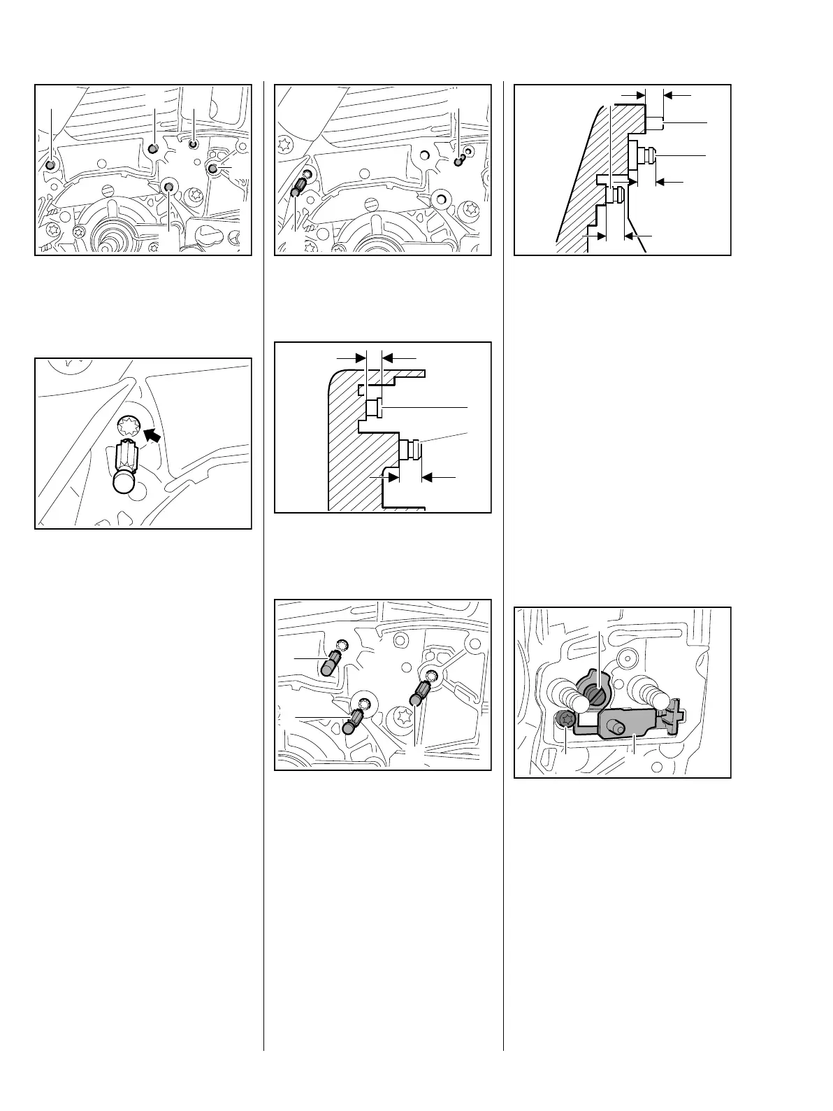
: Remove the pins (1) to (5).
Installing
– Before installing the new pin, coat
its knurled shank with
threadlocking adhesive, b 16
: Position the new pin in the bore
(arrow) so that the knurling on the
pin meshes with the existing
knurling in the bore.
The pins must be driven home
squarely.
1166RA020 TG
3
2 1
5
4
1166RA021 TG
: Drive home the pins (1 and 2) as
specified below.
: Pin (1) a = about 2.9 - 3.3 mm
Pin (2) b = about 4.3 - 4.7 mm
: Drive home the pins 3, 4 and 5)
as specified below.
1
2
1166RA022 TG
a
b
1166RA023 TG
1
2
1166RA024 TG
4
3
5
: Pin (3) a = about 9.9 - 10.1 mm
Pin (4) b = about 4.6 - 4.8 mm
Pin (5) c = about 5.1 - 5.3 mm
– Lubricate the brake lever and
cam lever with STIHL grease,
b 16
– Reassemble all other parts in the
reverse sequence.
5.6 Chain Tensioner
– Troubleshooting, b 3.2
– Remove the side plate, b 5.2
: Rotate the spur gear (1)
clockwise until the screw (2) is
visible.
: Take out the screw (2) and pull
out the tensioner (3).
– Remove the O-ring.
– Check individual parts of the
chain tensioner, replace if
necessary
a
c
b
3
4
5
1166RA025 TG
1166RA026 TG
1
2 3
 Loading...