43MS 661, MS 661 C-M
While using the ZAT 3, hold it only
by the handle (4) or position it in a
safe place. Keep fingers or other
parts of your body at least 1 cm
away from the spark window (3),
high voltage connection (2), ground
connection (5) and the ground
terminal (1).
High voltage – risk of electric shock.
– Crank the engine quickly with the
rewind starter and check spark in
the tester’s window (3).
The engine may start and
accelerate during the test.
If a spark is visible in the
window (3), the ignition system is in
order.
– If no spark is visible in the
window (2), check the ignition
system / M-Tronic with the aid of
the troubleshooting chart,
b 7.13, b 8.7
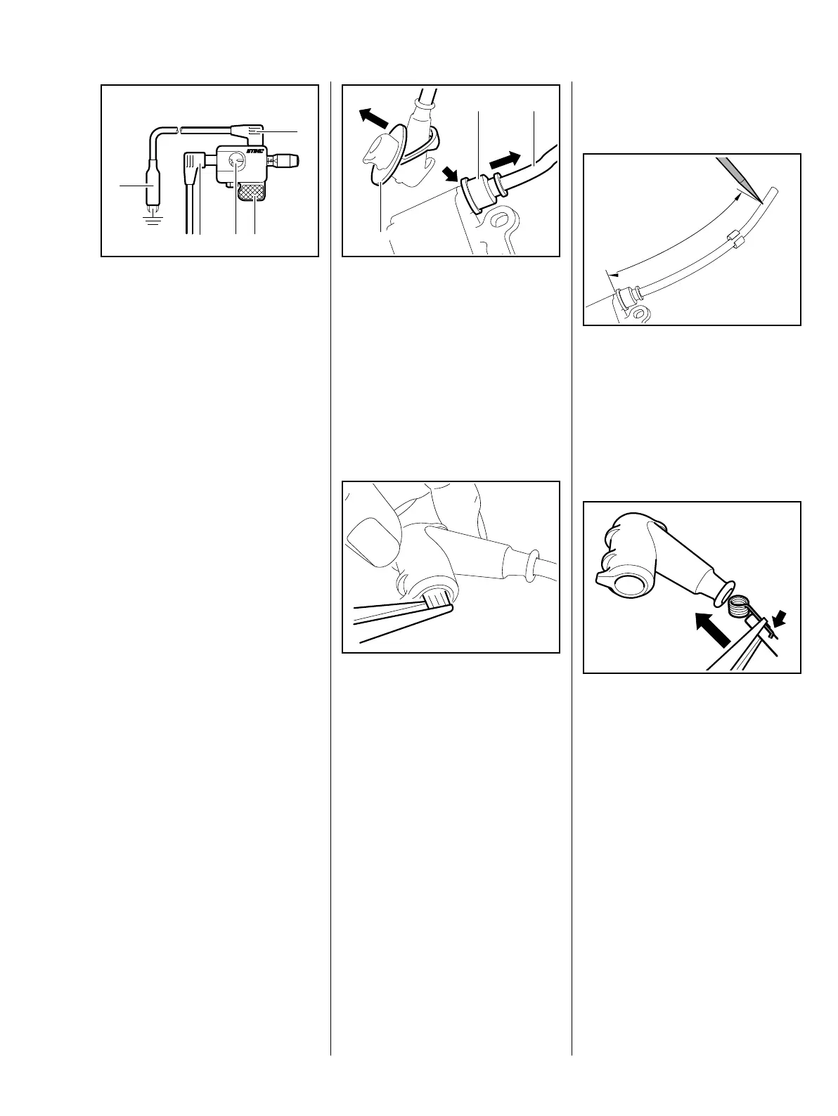
7.6 Spark Plug Boot /
Ignition Lead
– Remove the ignition module /
control unit, b 7.3
165RA185 TG
1
2
3 4
5
: Pull the grommet (1) off the high
voltage output (arrow).
: Unscrew the ignition lead (2)
from the ignition module / control
unit and pull the grommet (1) off
the ignition lead.
: Remove the cover (3) from the
spark plug boot.
: Use suitable pliers to pull the leg
spring out of the spark plug boot
and unhook it from the ignition
lead.
– Pull the spark plug boot and
cable retainer off the ignition
lead.
1166RA111 TG
1
3
2
6161RA167 TG
Installing
– Screw the ignition lead into the
ignition module / control unit.
: Use a pointed tool to pierce the
center of the ignition lead's
insulation at distance 'a' from the
ignition module / control unit.
– Models without M-Tronic:
a =195mm
– Models with M-Tronic:
a =197mm
: Pinch the hook of the leg spring
into the pierced hole in the center
of the lead (arrow).
– Coat the inside of the spark plug
boot with STIHL press fluid,
b 16
: Hold the ignition lead and leg
spring together and push them
into the spark plug boot.
1166RA450 TG
a
3443RA468 TG
 Loading...