52 MS 661, MS 661 C-M
Installing
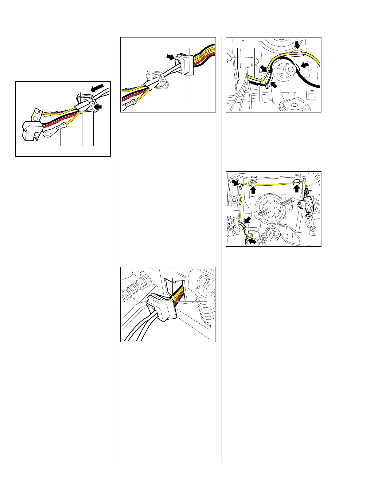
– If necessary, install the insulated
housing, b 7.10
: Line up the wiring harnesses with
the insulating tubes (1, 2) next to
one another and hold them
together.
: Position grommet (3) so that the
slope (arrow) faces the cable
lug (4), then push it over the
wiring harnesses at the end with
the ring terminals.
1166RA145 TG
31
2
4
: Position the grommet (4) so that
the contour (1) faces the wiring
harnesses insulating tubes (2, 3).
: Fit the wiring harness (2) with the
three wires through the lateral
opening (arrow) in the
grommet (4) so that the black
wire is at the bottom and the red
and yellow wires are in the order
shown.
: Fit the wiring harness (3) with the
two wires so that it is above
wiring harness (2) and the black
wire is at the top.
Do not cross the wires.
: Pass the wiring harnesses (1, 2),
ring terminals first, through the
opening from outside (cylinder
side) and into the carburetor box.
: Place the grommet (3) in
position, locate its groove and
slide it in sideways until the lug
engages at the other side.
1166RA146 TG
3
1
4
2
1166RA147 TG
1
2
3
Lug (1) must be engaged.
: Push the short circuit wire (2) and
ground wire (3) into the guides
(arrows).
: Push the ground wire (1) into the
guides (arrows) as shown and
connect the terminal (2) to the
heater switch (3) so that its
crimped side is facing the
manifold.
: Lay ground wire (1) close to
housing – loop (4) allows for
movement.
1166RA148 TG
1
2
3
1166RA455 TG
3
1
2
4
 Loading...