•
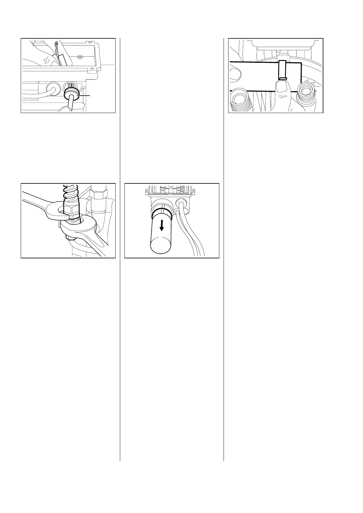
Press cable grommet (1) out of
housing and pull it out of the
housing with the power cable.
All models
•
Unscrew cable gland with fork
wrench:
- Wrench size 22 for upper nut
- Wrench size 24 for lower nut
- Check power cable, cable gland
and anti-kink tube and replace if
necessary.
Reassemble parts in reverse order.
- Remove shroud (see 5.1).
- Remove cover of switch housing
(see 9.2.1).
Note: Note circuit diagram; if
necessary, produce a drawing
clearly showing which wire
(note colour) is connected to the
respective terminals.
- Disconnect capacitor connecting
leads.
RE 140 K
•
Press capacitor out.
•
Check O-ring on capacitor and
replace if necessary.
- Replace defective parts.
RE 160 K
- Press cable grommet out of
housing and pull out of housing
with connecting lead (as for
power cable, see 9.2.3).
•
Release fastening clamp (1) and
pull capacitor out sideways.
- Remove fastening clamp if
necessary.
- Replace defective parts.
All models
Reassemble parts in reverse order.
- Ensure that O-ring and grommet
are correctly seated.
621RA039 BL 621RA038 BL
1
621RA112 KN
621RA040 BL
1
9.2.4 Capacitor
26 RE 140 K, 160 K

 Loading...