5 Electrical Installation User Manual
22
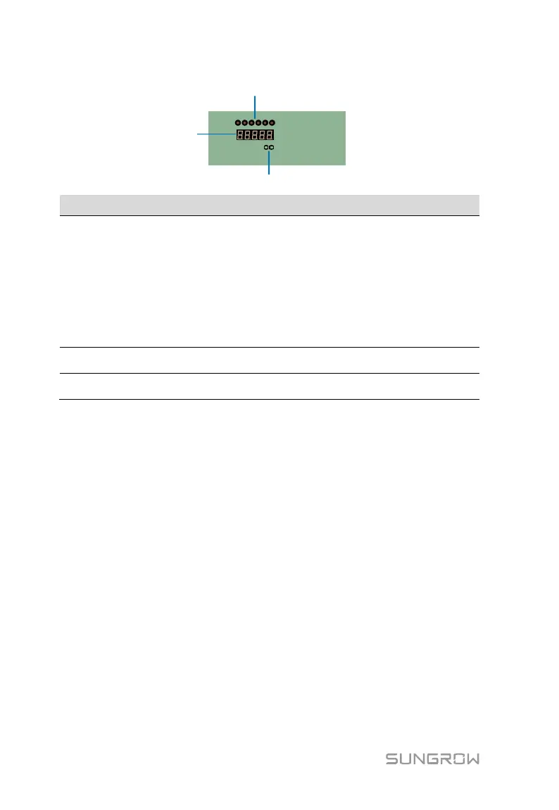
From left to right, the indicators are respectively:
TX: Transmitted communication data signal indicator
RX: Received communication data signal indicator
RUN: Monitoring unit running status indicator
SPD: Surge protection device fault indicator
CB: Load-break switch status indicator
POWER: Monitoring unit power supply status indicator
Key buttons K1 and K2 (used for switching current, communication and
other parameters)
LED display (display current, baud rate, communication address,
chassis temperature, etc.)
SPD (Surge Protection Device)
An SPD is equipped inside the PVS to prevent the transient overvoltage caused
by lightning. The SPD failure signal can be sent to the PC through the RS485.
Grounding
It must be grounded properly for overvoltage protection. The PVS provides a
ground terminal for grounding connection.
5.2 Waterproof Terminal
Waterproof terminals such as input, output, communication and grounding
terminals are installed at the bottom of the combiner box, and the
corresponding terminal marks are shown in the following table.
 Loading...