8. V-BELT DRIVING SYSTEM/KICK STARTER ARM SYM
8-2
LEFT CRANKCASE COVER
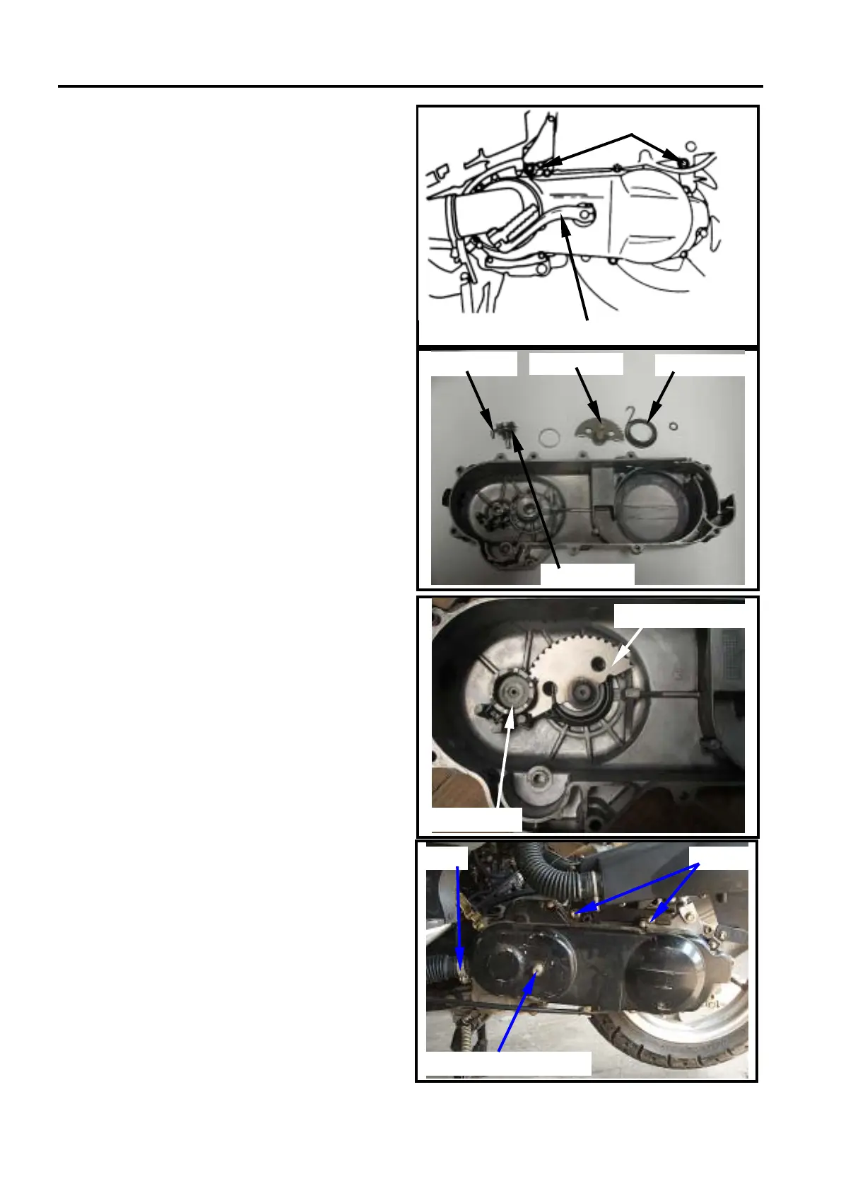
Left crankcase cover removal
Remove air cleaner. (2 bolts)
Remove kick starter arm. (1 bolt)
Loosen vent strap on the front-left side of
cover, and then remove the vent.
Remove engine left-side cover (8 bolts).
KICK STARTER ARM
Disassembly
Remove the return spring, starter shaft.
Remove driving gear, friction spring and
washer.
Inspection
Check if starter shaft, driving gear, for wear
or damage. Replace it with new one if
necessary.
Check the return spring for spring force or
damaged. Replace it with one if poor parts
found.
Reassembly
Apply with some specified grease on the
gear, shaft.
Install the friction spring of driving gear onto
convex part of the case cover.
Install, return spring and starter shaft as
diagram shown.
Install kick starter arm temporary.
Rotate the lever and then align driving gear
with width-tooth on the starter shaft.
Install thrust washer and socket onto starter
shaft.
Installation of the left crankcase
cover
Install the left crankcase cover. (8 bolts)
Install front vent tube of left cover and tighten
the strap.
Install kick starter arm. (1 bolt)
Tighten the air cleaner. (2 bolts)
air cleaner lock nut
kick starter arm
Return spring
Starter shaft
Starter shaft
Friction spring
Driving gear
driving gear
starter shaft gear
Kick starter arm shaft
Strap Bolts
 Loading...