English
The mains hydraulic circuit will provide a constant water ow on the refrigerating uid/water plate
exchanger and in case of load variation.
Caution
When choosing and installing water pipes, you must consult and observe all current local standards,
regulations and instructions.
Caution
The expansion tank must be dimensioned to be able to absorb an expansion corresponding to 2%
total volume of water contained in the installation (exchanger, piping, installations and buffer tank,
if present).
Caution
THE WARRANTY DOES NOT COVER DAMAGE DUE TO CORROSION RESULTING FROM ELECTROLYTIC
PHENOMENA.
Caution
To avoid any risk of foreign bodies entering the appliance and to guarantee operating performance,
IT IS IMPERATIVE TO INSTALL WATER FILTER on the SysAqua inlet pipe.
Caution
THE MANUFACTURER'S WARRANTY IS VOID IF THE FILTER SUPPLIED WITH
THE SysAqua IS NOT INSTALLED TO PROTECT THE APPLIANCE
Caution
14 SysAqua
10. HYDRAULIC LINKS
10.1. MAIN HYDRAULIC CIRCUIT
You must design the pipe network with the minimum number of bends and keep the number of changes in
height to the strict minimum. This will reduce installation costs and ensure optimum system performance.
The pipe network must include:
² A vibration elimination system (e.g.: link hoses available as an accessory) on all pipes connected to
the appliance in order to reduce vibrations and noise transmitted to the building fabric.
² A balancing valve on the water outlet pipe in order to control the water ow balance.
² Stop cocks to isolate the hydraulic circuit during maintenance.
² Manual or automatic bleed valves at the highest point on the water circuit.
² Draining connectors at all low points to allow complete circuit draining
² A circulation pump guaranteeing ow and manometric height necessary for the operation of the
SysAqua unit.
² A diaphragm expansion tank tted with a safety and draining valve must be visible.
² A low water pressure sensor to secure the water pump against cavitation if the water pressure in the
circuit decreases.
² The installation of thermometers and pressure gauges on the heat exchanger inlet and outlet to
facilitate day-to-day controls and system maintenance.
² An element ensuring ground continuity of all piping. An unbalance of grounding connection points
can cause corrosion problems due to electrolytic phenomena.
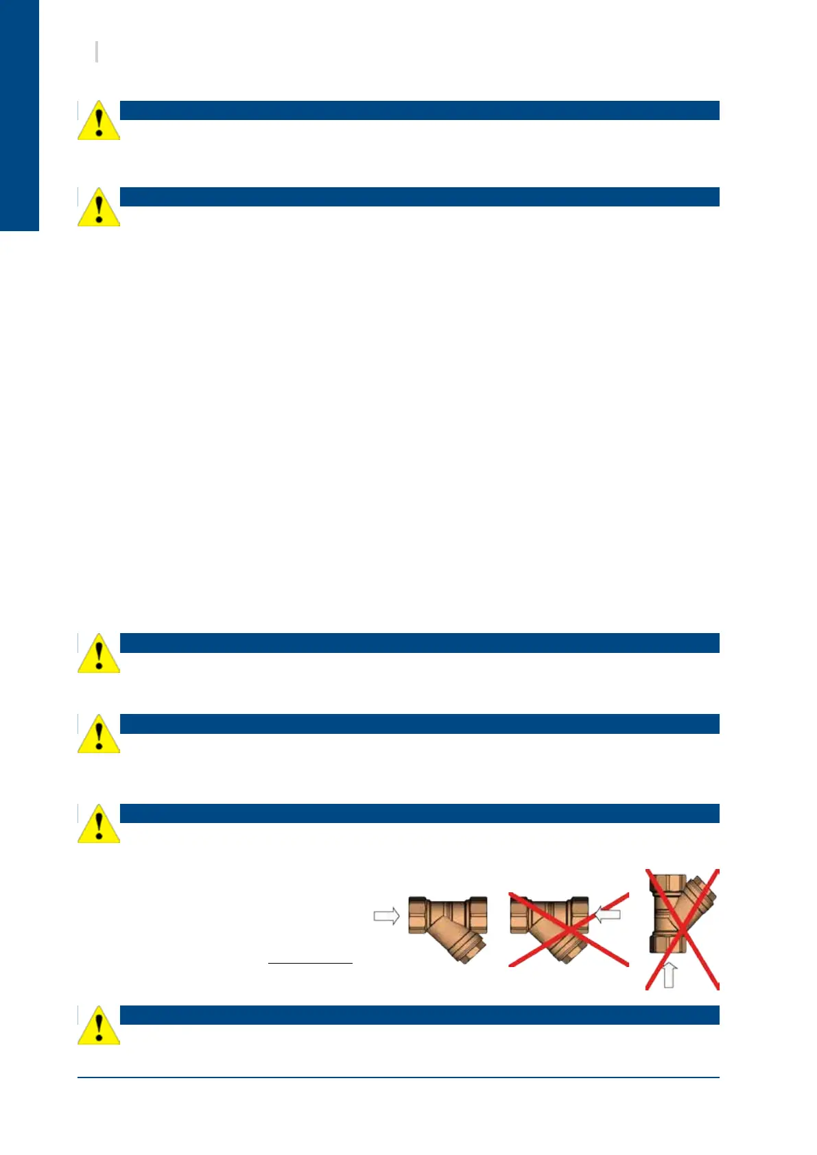
10.2. ANTI-CLOGGING PROTECTION
By default, the SysAqua plate exchanger
would be clogged soon after start-up.
Proper operation of the SysAqua would
be disturbed by the reduced water ow. In
case of insufcient water ow, the plate
exchanger would be damaged IRREVERSIBLY.
The mesh size of the lter must be lower than
800 µm.
 Loading...


