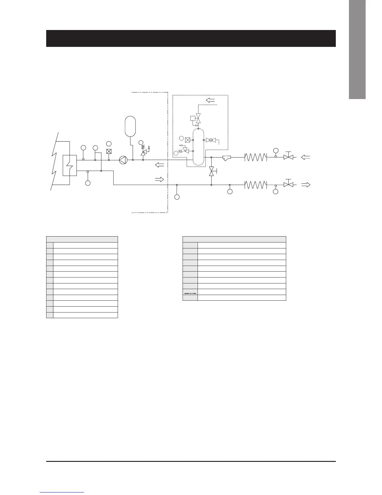
External water circuit SYSCROLL 20-35 Air CO/HP - R410A
4 - Installation
SAFETY/CONTROL DEVICES
A Inlet water temperature sensor
B Outlet water temperature sensor
C Water differential pressure switch (105 mbar)
D Vent valve
E Water safety valve (3 bar)
F Manometer
FS Flow switch
G Thermometer
Unit side
Y Water drain
10
10
9 9
13
12
12 11
11
4
5
3
8
6
HYDROKIT
INLET
OUTLET
Y
2
1
7
FS
F
E
E
D
D
C
A
B
G
G
COMPONENTS
1 Plate heat exchanger
2 Pump
3 Draining valve
4 Water buffer tank
5 Water filter
6 Automatic water charging valve
7 Pressure expansion tank
8 Water charging line
9 Water outlet
10 Water inlet
11 Globe valve
12 Flexible pipes
13 By-pass valve
 Loading...


