7 - Product Description
3
2
ON
H
4
5
6
7
8
AT
A
1
C
FS
N
11
N
L
L
12
10
15
15
14
16
13
HYDROKIT
9
17
S
F
E
D
I
S
B
S
KM
KM
MECHANICAL EXPANSION VALVE
(STANDARD)
6
5
4
ELECTRONIC EXPANSION
VALVE (OPTIONAL)
BT
EEV
CONTROL
UNIT
CONTROL
ST
S
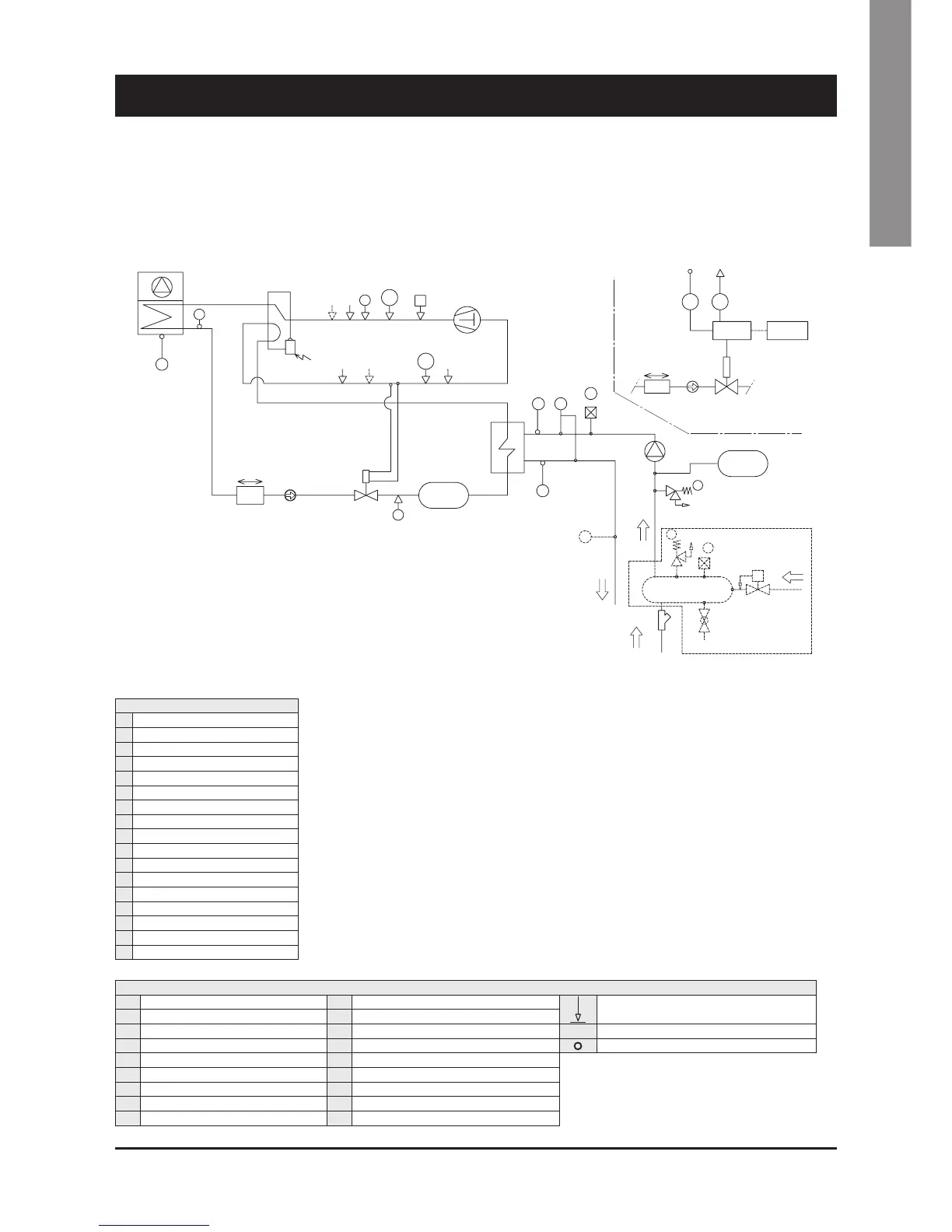
SAFETY/CONTROL DEVICES
A
High pressure switch
H
Defrost temperature sensor
Pipe connection with Shrader valve
AT
High pressure transducer
I Discharge gas thermostat - DGT
BT
Low pressure transducer
L
Vent valve
-------
Optional parts
B Low pressure switch N
Water safety valve
Sensors
C
Water differential pressure switch
S
Shrader valve
(service/
charging point
)
D
Air temperature sensor
ST Suction temperature probe
E
Outlet water temperature sensor
KM Gauge kit (optional)
F
Inlet water temperature sensor
FS
Flow switch
COMPONENTS
1 Compressor Scroll
2 4-way valve
3 Air cooled condenser
4 Biflow filter drier
5 Sight glass
6 Biflow thermostatic expansion valve
7 Liquid receiver
8 Plate heat exchanger
9 Pump
10 Drain valve
11 Water buffer tank
12 Water filter (loose)
13 Automatic water charging valve
14 Water outlet
15 Water inlet
16 Water charging line
17 Pressure expansion tank
Refrigerant flow diagram - SYSCROLL 20-35 Air HP - R410A
 Loading...


