4.6 Power supply
DANGER
Before carrying out any operations on the
electrical system, make sure that the unit is
deenergized.
DANGER
It is important that the appliance is grounded.
WARNING
The company in charge of the installation shall
conform to the standards applicable to outdoor
electrical connections.
The manufacturer may not be held liable for any damage
and/or injury caused by failure to comply with these
precautions.
The unit conforms to EN 60204-1.
The following connections shall be provided:
!
A 3-phase and grounding connection for the power supply circuit.
!
The electrical distribution system shall meet the power absorbed
by the appliance.
!
The disconnecting and magnetothermal switches must be sized
to control the starting current of the unit.
!
The power supply lines and the insulation devices must be
designed in such a way that every line independent.
!
It is recommended to install differential switches, to prevent any
damage caused by phase drops.
!
The fans and compressors are supplied through contactors
controlled from the control panel.
!
Each motor is provided with an internal safety thermal device and
external fuses.
!
The power supply cables must be inserted into dedicated
openings on the front of the unit, and the will enter the electrical
board through holes drilled on the bottom of the board.
4 - Installation
CAUTIONS
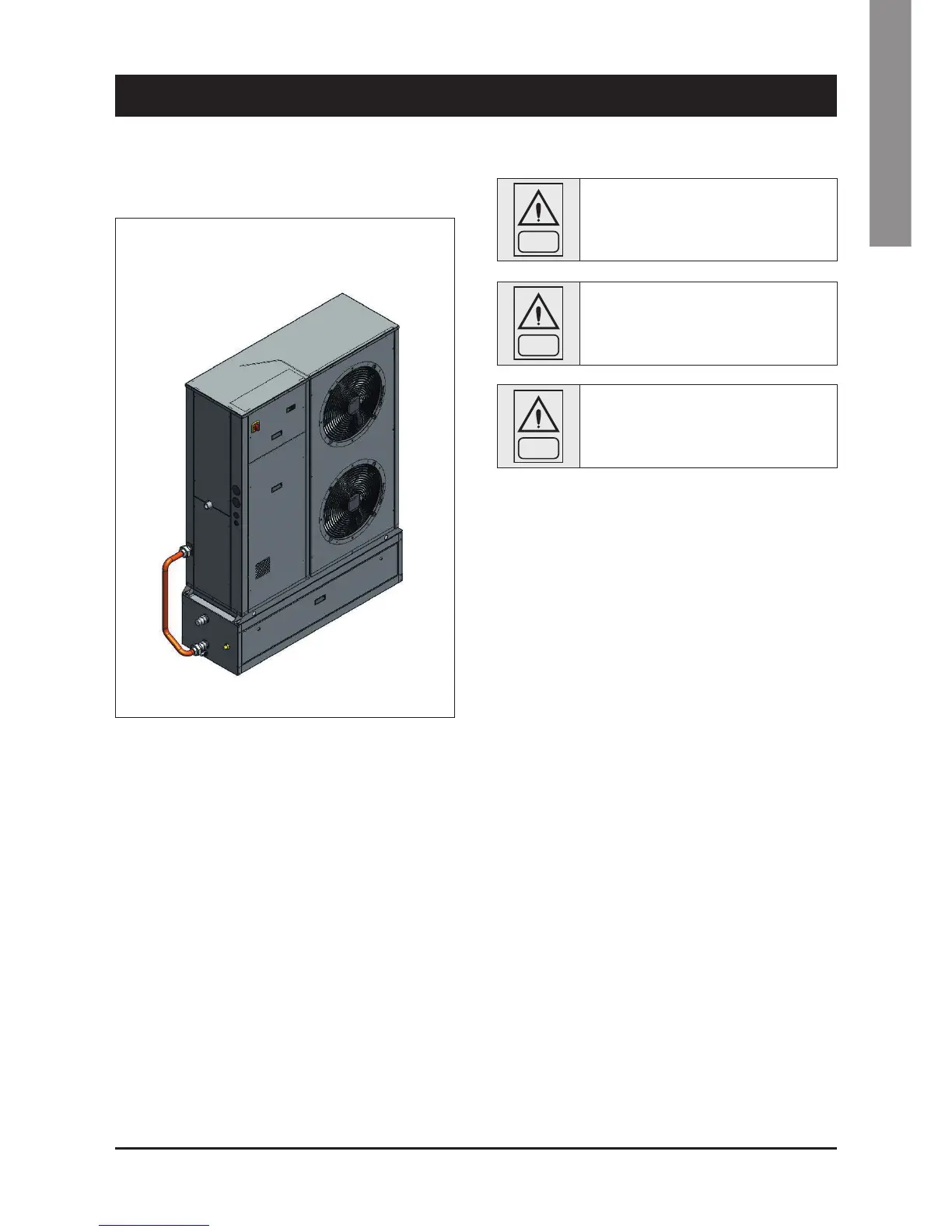
The unit + tank system shall be equipped with a filter. Use the filter
+ union as it is shown by Figure 1.
Figure 1
4.5.5 Installation Procedure
For the size 20-35 the hydrokit shall be arranged beneath the unit. It
will not change its overall dimensions (Figure 1).
Arrange the rubber shock absorbers beneath the kit before providing
for its connection.
Provide for the hydraulic and electrical connections. Doing that,
observe the diameters shown by the quoted drawings.
The wiring for the standard antifreeze resistance is arranged as it is
shown by . The resistance is connected with the main terminal box.
See the wiring diagram attached to the unit for the correct execution
of the electrical connections.
Install the water filter as it is shown by Figure 1.
 Loading...


