M2000-00
T2000-A66 Single Port UART Kit
8.13.3
Copyright TEL 31/12/97
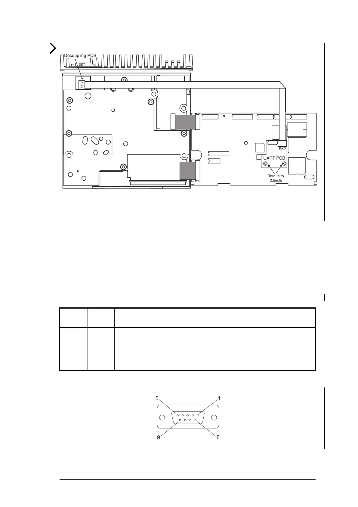
Figure 8.13.1 T2000-A66 Single Port UART PCB Mounting
4 Fold the T2000-A66 loom as shown, then plug into SKT2 on the decoupling PCB.
5 Fold the logic PCB back in position, and secure using the three logic PCB retaining
screws and refit the top cover.
8.13.3 Signal Specifications
The following table describes the signals used on the decoupling PCB 9 way D-range
connector (SKT1). The unused pins may be used for other signals, if required.
The following diagram shows the pin designations of SKT1, viewed from the rear of the
radio.
Figure 8.13.2 9 Way D-Range Connector (SKT1)
SKT1
Pin No.
Signal Description
2TXDTransmit data: Serial data output from UART PCB. This signal complies
with the electrical requirement s of the RS-232 specification.
3RXDReceive data: Serial data input to UART PCB. This signal complies with
the electrical requirements of the RS-232 specification.
5DGNDDigital ground: Ground reference for all digital signals.
2
 Loading...