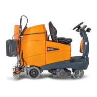
35
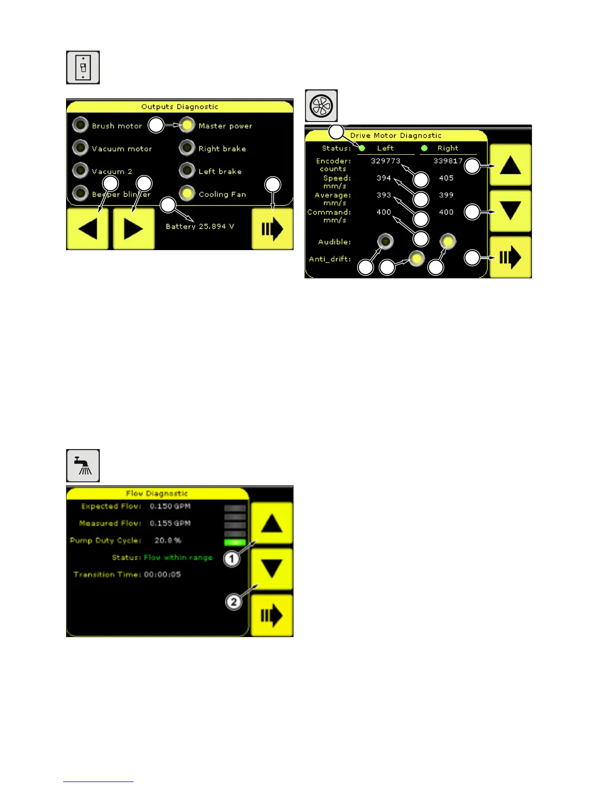
41. Outputs Diagnostic
The outputs diagnostic is used to aid in
system troubleshoot by allowing privileged
operators to turn on specic machine
devices and verify their operation.
5
4
2 3
1
Figure: 64
1 Output on/off button
2 Cycle backward through output screens
3 Cycle forward through output screens
4 Battery voltage display
5 Return to diagnostics main screen
Cycle through the output screens by pressing the next (3)and
previous (2) keys. Press the desired output (1) to cycle on or
off.
The current battery voltage (4) is displayed during the
diagnostic test.
42. Flow Diagnostic
The ow diagnostic allows for testing and
troubleshooting of the pumping system.
Figure: 65
Pressing the up (1) arrow will increase the system ow rate
and start a priming cycle. The cycle may be terminated by
pressing the down arrow (2).
Priming may take up to two minutes. A priming failure may
indicate an air leak in the plumbing, check for loose canisters
or missing o-rings and restart the diagnostic.
Once priming is complete, the measured ow rate should be
within 0.03 gpm (0.11 lpm) of the expected ow rate.
43. Drive Motor Diagnostic
The drive motor diagnostic utility provides
information used by a trained service
technician to calibrate the drive motors.
2
3
4
5
6 67
8
9
10
Figure: 66
1 Amplier status indicator
2 Encoder counts
3 Speed mm/s
4 Average mm/s
5 Command mm/s
6 Audible alert
7 Anti-drift
8 Step the command speedup
9 Step the command speed down
10 Return to diagnostics main screen
The diagnostic can be used to verify the status of the drive
ampliers by checking the Status lights (1). Green lights
indicate the drive amplier is operational, a red light indicates
a fault.
 Loading...