5-4
USER INTERFACE
Model C722
User Interface
5
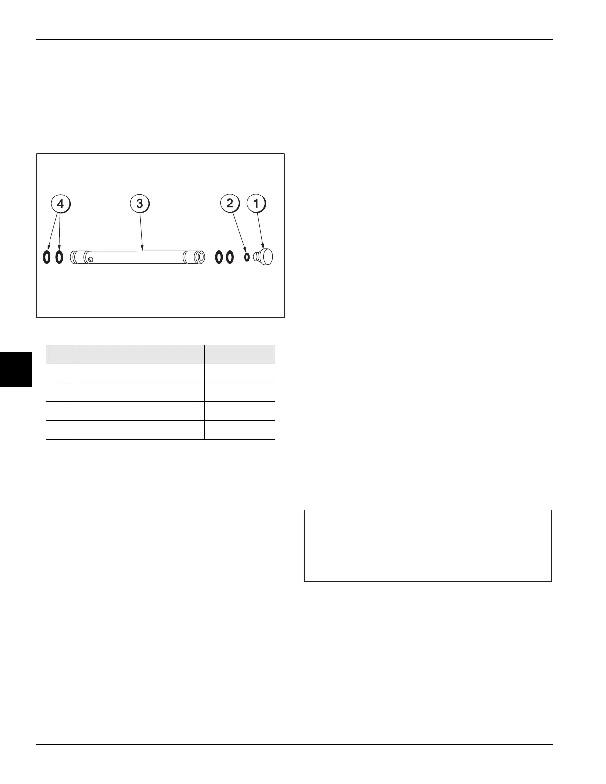
Optional Feed Tube (Back-up Option)
If the air/mix pump has become inoperable because of a
missing or damaged part, the operator can temporarily
operate the unit using the feed tube. The product ejection
rate will be slower when the feed tube is used instead of
the air/mix pump.
Figure 5-3
The feed tube serves two purposes. One end of the tube
has a hole and the other end does not.
1. Normal Operation
During normal operation, the end of the feed tube
with the hole is placed into the mix inlet hole. Every
time the draw handle is raised, new mix and air from
the hopper flow into the freezing cylinder. This keeps
the freezing cylinder properly loaded and maintains
overrun.
2. Long “No Sale” Periods
During long “No Sale” periods, the unit can be placed
into the Standby mode. This maintains product
temperatures below 40°F (4.4°C) in both the hopper
and the freezing cylinder, and helps prevent over-
beating and product breakdown.
To place the unit into the Standby mode, press the
STANDBY key. Remove the air orifice. Lubricate the
o-rings located on the end of the feed tube without the
hole. Place that end of the tube into the mix inlet hole.
This will prevent any mix from entering the freezing
cylinder.
Note: The air orifice is used to meter a certain amount
of air into the freezing cylinder. The air orifice maintains
overrun and allows enough mix to enter the freezing
cylinder after a draw.
Operating Screen Descriptions
The LCD located in the center of the control panel is
normally blank during the daily operation of the machine.
The display is activated when the SEL symbol or the
Manager's Menu is selected. The display screen will also
alert the operator of specific faults detected by the
control.
Power Up
When the machine is powered, the control system will
initialize to perform a system check. The screen will
display INITIALIZING. There are four types of data the
system will check: LANGUAGE, SYSTEM DATA,
CONFIG DATA, and LOCKOUT DATA.
If the system detects corrupt data during “initializing.....,”
the detected faults will be displayed for acknowledgment
after the SAFETY TIMEOUT display, if the power switch
is on. The faults may be CORRUPTED LANGUAGE,
CONFIG CRC ERR, SYSTEM CRC ERR, FAULT
HISTORY, LOCKOUT CRC ERR, or POWER FAILURE.
Once the system has initialized, the number of days
remaining before the next required brush-cleaning is
indicated on the control panel and the SAFETY
TIMEOUT screen is displayed with the alarm turned on.
The SAFETY TIMEOUT screen will be displayed with the
alarm on for 60 seconds, or until any control symbol is
selected.
Item Description Part No.
1 Orifice 022465-100
2 O-ring-3/8 OD X .070 W 016137
3 Tube A.-Feed-SS 5/32 Hole X29429-2
4 O-ring-.643 OD X .077 W 018572
SAFETY TIMEOUT
ANY KEY ABORTS
 Loading...