
W
William CookAug 19, 2025
What to do if TECO Servo Drives show over-voltage error?
- JJohn SpencerAug 19, 2025
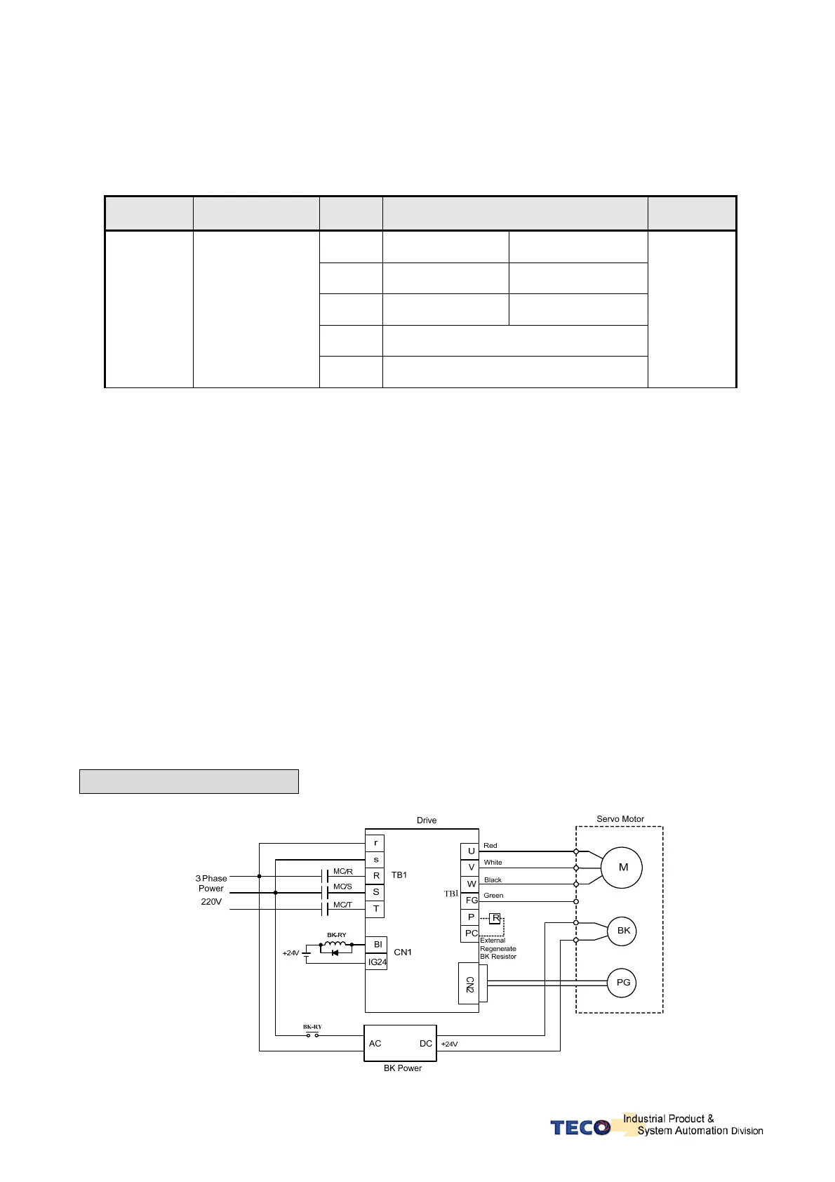
If your TECO Servo Drive displays an over-voltage (regeneration error), it means the main circuit voltage has exceeded the maximum allowable value (410V). First, use a multimeter to check if the input voltage is within the specified limit. Next, verify that Parameter Cn012 is set correctly. If the alarm appears during operation, extend the acceleration/deceleration time or reduce the load ratio within the permitted range. If the problem persists, an external regeneration resistor might be needed.