4-6
B. Trial run in Speed control mode(Cn001=1).
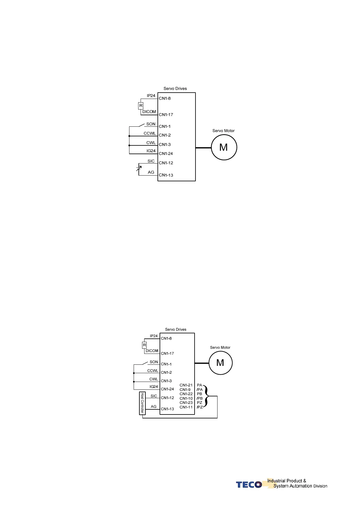
1. Wiring check:
Check and ensure that all power cable and control signal connections are correct as shown below.
To be able to adjust the speed for test connect a potentiometer between terminals SIN (analog input
voltage) and AG (Analog Ground). Set the analog input voltage to 0V. (No speed reference).
2. Apply Servo on.
Apply power to the drive and activate (SON) signal by switching SON terminal to IG24 (input digital
Ground). If the motor rotates slowly, while the speed analog input voltage is 0 volts
then use dn-07 function to auto offset adjustment for the analog input value. (refer to section 3-2-2).
3. Check the relationship between motor speed and the analog input speed command.
Increase the analog speed input voltage gradually (by potentiometer) and monitor the actual motor
speed by parameter Un0-01.
Check if motor rotation direction is correct and if necessary set it by parameter Cn004.
Check for correctness of analog speed command ratio in relation to the preset in parameter (Sn216) and
analog speed command limit as set in parameter (Sn218).
Finally, switch off SON signal (turn off the servo motor).
4. Connection with a host controller.
Check and ensure that the wiring for the servo drive and host controller, speed analog signal input (SIN),
and encoder output (PA, /PA, PB, /PB, PZ, /PZ) are all correct and according to the diagram below:
5. Confirm the rotation number and encoder output of Servo Motor.
Use parameter Un-14 to check if the Motor feed back (number of revolutions) per minute is correct and
the same as number of revolutions sent by the host controller.
If there is any difference then check and make sure that parameter Cn005 ( Encoder ppr) is set correctly.
Once this is complete remove SON signal to switch off power to the motor.
 Loading...