Preparation For Use—2213A Operators
VERTICAL
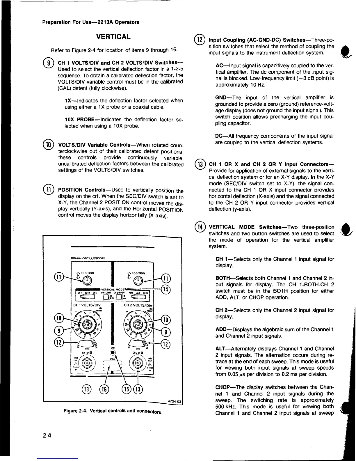
Refer to Figure 2-4 for location of items 9 through 16.
(jT ) CH 1 VOLTS/DIV and CH 2 VOLTS/DIV Switches—
Used to select the vertical deflection factor in a 1-2-5
sequence. To obtain a calibrated deflection factor, the
VOLTS/DIV variable control must be in the calibrated
(CAL) detent (fully clockwise).
IX — Indicates the deflection factor selected when
using either a 1X probe or a coaxial cable.
10X PROBE—Indicates the deflection factor se
lected when using a 10X probe.
® VOLTS/DIV Variable Controls—When rotated coun
terclockwise out of their calibrated detent positions,
these controls provide continuously variable,
uncalibrated deflection factors between the calibrated
settings of the VOLTS/DIV switches.
POSITION Controls—Used to vertically position the
display on the crt. When the SEC/DIV switch is set to
X-Y, the Channel 2 POSITION control moves the dis
play vertically (Y-axis), and the Horizontal POSITION
control moves the display horizontally (X-axis).
Figure 2-4. Vertical controls and connectors.
^ 2 ) Input Coupling (AC-GND-DC) Switches—Three-po
sition switches that select the method of coupling the
input signals to the instrument deflection system.
AC—Input signal is capacitively coupled to the ver
tical amplifier. The dc component of the input sig
nal is blocked. Low-frequency limit (-3 dB point) is
approximately 10 Hz.
GND—The input of the vertical amplifier is
grounded to provide a zero (ground) reference-volt
age display (does not ground the input signal). This
switch position allows precharging the input cou
pling capacitor.
DC—All frequency components of the input signal
are coupled to the vertical deflection systems.
(l3 ) CH 1 OR X and CH 2 OR Y Input Connectors—
Provide for application of external signals to the verti
cal deflection system or for an X-Y display. In the X-Y
mode (SEC/DIV switch set to X-Y), the signal con
nected to the CH 1 OR X input connector provides
horizontal deflection (X-axis) and the signal connected
to the CH 2 OR Y input connector provides vertical
deflection (y-axis).
M4J VERTICAL MODE Switches—Two three-position
switches and two button switches are used to select
the mode of operation for the vertical amplifier
system.
CH 1—Selects only the Channel 1 input signal for
display.
BOTH—Selects both Channel 1 and Channel 2 in
put signals for display. The CH 1-BOTH-CH 2
switch must be in the BOTH position for either
ADD, ALT, or CHOP operation.
CH 2—Selects only the Channel 2 input signal for
display.
ADD— Displays the algebraic sum of the Channel 1
and Channel 2 input signals.
ALT—Alternately displays Channel 1 and Channel
2 input signals. The alternation occurs during re
trace at the end of each sweep. This mode is useful
for viewing both input signals at sweep speeds
from 0.05 iis per division to 0.2 ms per division.
CHOP—The display switches between the Chan
nel 1 and Channel 2 input signals during the
sweep. The switching rate is approximately
500 kHz. This mode is useful for viewing both
Channel 1 and Channel 2 input signals at sweep
2-4

 Loading...


