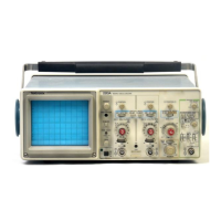
Operators Familiarization—2213A Operators
OPERATOR’S ADJUSTMENTS
INTRODUCTION trig g e r
To verify the operation and accuracy of your instrument
before making measurements, perform the following adjust
ment procedures. If adjustments are required beyond the
scope of the operators’s adjustments, refer the instrument
to a qualified service technician.
VAR HOLDOFF
Mode
SLOPE
LEVEL
INT
SOURCE
EXT COUPLING
NORM
P-P AUTO
OUT
Midrange
VERT MODE
INT
AC
Before proceeding with these instructions, refer to
“Preparation for Use” (Section 2).
Verify that the POWER switch is OFF (button out), then
plug the power cord into the power-source outlet.
2. Press in the POWER switch button (ON) and allow the
instrument to warm up (20 minutes is recommended for
maximum accuracy).
3. Adjust the INTENSITY control for desired display
If indications specified in these procedures cannot be ob- brightness,
tained, refer the instrument to a qualified service technician.
4. Adjust the Vertical and Horizontal POSITION controls
as needed to center the trace on the screen.
BASELINE TRACE
First obtain a baseline trace, using the following
procedure.
1. Preset the instrument front-panel controls as follows:
TRACE ROTATION
Normally, the resulting trace will be parallel to the center
horizontal graticule line, and the Trace Rotation adjustment
should not be required. If adjustment is needed, perform the
following procedure:
Display
INTENSITY
FOCUS
Fully counterclockwise 1 • Preset instrument controls and obtain a baseline
Midrange trace.
Vertical (Both Channels)
POSITION
VERTICAL MODE
BW LIMIT
VOLTS/DIV
VOLTS/DIV Variable
CH 2 INVERT
Input Coupling
Midrange
CH 1
Off (button out)
50 mV
CAL detent
Off (button out)
AC
2. Use the Channel 1 POSITION control to move the
baseline trace to the center horizontal graticule line.
3. If the resulting trace is not parallel to the center hori
zontal graticule line, use small flat-bit screwdriver to adjust
the TRACE ROTATION control and align the trace with the
center horizontal graticule line.
Horizontal
POSITION
HORIZONTAL MODE
SEC/DIV
SEC/DIV Variable
X I0 Magnifier
Range Selector
MULTIPLIER
Midrange
NO DLY
0.5 ms
CAL detent
Off (knob in)
0.4 ms
<X1
PROBE COMPENSATION
Misadjustment of probe compensation is a common
source of measurement error. Most attenuator probes are
equipped with a compensation adjustment. To ensure opti
mum measurement accuracy, always compensate the oscil
loscope probes before making measurements. Probe
compensation is accomplished as follows:
3-3

 Loading...