Preparation For Use—2213A Operators
TRIGGER
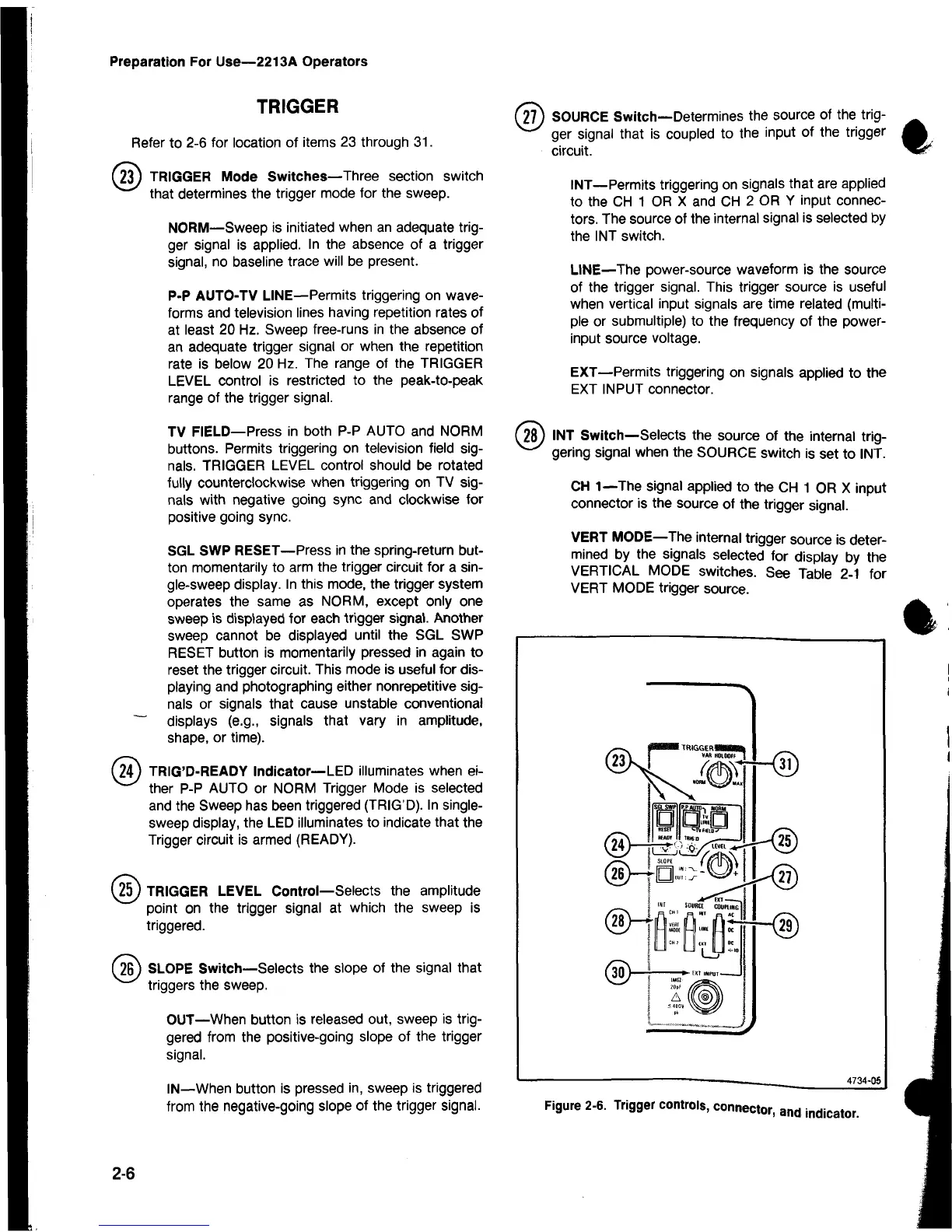
Refer to 2-6 for location of items 23 through 31.
(23) TRIGGER Mode Switches—Three section switch
that determines the trigger mode for the sweep.
NORM—Sweep is initiated when an adequate trig
ger signal is applied. In the absence of a trigger
signal, no baseline trace will be present.
P-P AUTO-TV LINE—Permits triggering on wave
forms and television lines having repetition rates of
at least 20 Hz. Sweep free-runs in the absence of
an adequate trigger signal or when the repetition
rate is below 20 Hz. The range of the TRIGGER
LEVEL control is restricted to the peak-to-peak
range of the trigger signal.
TV FIELD— Press in both P-P AUTO and NORM
buttons. Permits triggering on television field sig
nals. TRIGGER LEVEL control should be rotated
fully counterclockwise when triggering on TV sig
nals with negative going sync and clockwise for
positive going sync.
SGL SWP RESET—Press in the spring-return but
ton momentarily to arm the trigger circuit for a sin
gle-sweep display. In this mode, the trigger system
operates the same as NORM, except only one
sweep is displayed for each trigger signal. Another
sweep cannot be displayed until the SGL SWP
RESET button is momentarily pressed in again to
reset the trigger circuit. This mode is useful for dis
playing and photographing either nonrepetitive sig
nals or signals that cause unstable conventional
~ displays (e.g., signals that vary in amplitude,
shape, or time).
( S ) TRIG’D-READY Indicator— LED illuminates when ei-
v> ther P-P AUTO or NORM Trigger Mode is selected
and the Sweep has been triggered (TRIG’D). In single
sweep display, the LED illuminates to indicate that the
Trigger circuit is armed (READY).
(
25
) TRIGGER LEVEL Control—Selects the amplitude
point on the trigger signal at which the sweep is
triggered.
(26) SLOPE Switch—Selects the slope of the signal that
triggers the sweep.
OUT—When button is released out, sweep is trig
gered from the positive-going slope of the trigger
signal.
IN—When button is pressed in, sweep is triggered
from the negative-going slope of the trigger signal.
(27) SOURCE Switch— Determines the source of the trig-
ger signal that is coupled to the input of the trigger
circuit.
INT— Permits triggering on signals that are applied
to the CH 1 OR X and CH 2 OR Y input connec
tors. The source of the internal signal is selected by
the INT switch.
LINE—The power-source waveform is the source
of the trigger signal. This trigger source is useful
when vertical input signals are time related (multi
ple or submultiple) to the frequency of the power-
input source voltage.
EXT—Permits triggering on signals applied to the
EXT INPUT connector.
(2 8 ) INT Switch—Selects the source of the internal trig-
gering signal when the SOURCE switch is set to INT.
CH 1—The signal applied to the CH 1 OR X input
connector is the source of the trigger signal.
VERT MODE—The internal trigger source is deter
mined by the signals selected for display by the
VERTICAL MODE switches. See Table 2-1 for
VERT MODE trigger source.
"N
--------------------------------------------------------------
—
_
_________________
4734-os
Figure 2-6. Trigger controls, connector, and indicator.
2-6

 Loading...


