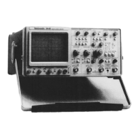
Controls, Connectors, and Indicators—2445 Operators
set to GND or when the input coupling of both
Channel 1 and Channel 2 is set to GND, with
ADD VERTICAL MODE and VERT TRIGGER
SOURCE selected.
SGL SEQ—When armed by pushing the MODE
switch down momentarily, the sweep runs one or
more times to produce a single sweep of each of
the traces defined by the following controls:
VERTICAL MODE, A and B SEC/DIV, and At.
Each sweep requires a distinct A Sweep triggering
event. The READY indicator remains illuminated
until the final trace in the sequence is completed.
At the end of the sequence the crt readout is
written once to present scale factors and other
readout data, and scale illumination flashes on
momentarily for oscilloscope photography
purposes.
B Trigger Modes:
RUN AFT DLY—The B Sweep runs immediately
after the established delay time has elapsed.
Delay time is set by the A SEC/DIV switch and
the A POS OR DLY REF control when no Delta
Time measurements are selected (neither At nor
1/At).
When either At or 1/At measurements are made,
two delay times are established: one by the A
REF OR DLY POS control and the other by the
A control.
TRIG AFT DLY—The B Sweep runs when trig
gered by a triggering signal after the established
delay time has elapsed, provided the A Sweep has
not terminated. Since the B Sweep runs at the
time the triggering signal occurs, the display is
stable, even with jittering signals; but the actual
delay time is greater than the delay-time setting.
Therefore, the crt readout shows a question mark
in this mode.
(3?) SOURCE Switch and Indicators—Selects the trigger
signal source for either the A or the B Sweep.
Indicators show the selection made. A single push of
the switch steps the SOURCE selection once; holding
the switch up or down causes the SOURCE selection
to step repeatedly. Indicators do not illuminate for
B triggering signals when RUN AFT DLY is selected.
VERT—The sweep triggers on the displayed
channel when only one channel is selected. If
multiple vertical displays are selected, both the
Trigger MODE in use and position of the CHOP/
ALT button affect the trigger-source selection.
When ALT VERTICAL MODE is selected, each
displayed channel in turn provides the triggering
signal, and the respective LED indicator for each
displayed channel is illuminated, except in the case
of AUTO LVL MODE triggering. For AUTO LVL
triggering or CHOP VERTICAL MODE, the lowest
numbered channel, or ADD if it is displayed, is the
triggering-signal source. The LED indicator for the
lowest numbered channel displayed is illuminated,
except if ADD is selected. Then, the CH 1, CH 2,
and VERT indicators are illuminated.
CH 1, CH 2, CH 3, or CH 4—A triggering signal is
obtained from the corresponding vertical channel.
LINE (A Trigger Only)—A triggering signal is
obtained from a sample of the ac power-source
waveform. This trigger source is useful when
vertical input signals are time related (multiple or
submultiple) to the frequency of the ac power-
source voltage.
(3?) COUPLING Switch and Indicators—Selects the
method of coupling the triggering signal to the A and
the B trigger generator circuitry. A single push of the
switch steps the COUPLING selection once; holding
the switch up or down causes the COUPLING selec
tion to step repeatedly. Indicators show the coupling
method selected for either the A triggering signals
(when an A TRIGGER MODE is in effect) or the B
triggering signals when TRIG AFT DLY is selected
for the B TRIGGER MODE. Indicators do not
illuminate for B triggering signals when RUN AFT
DLY is selected.
DC—All frequency components of the signal are
coupled to the trigger-generator circuitry. This
coupling method is useful for triggering on most
signals.
NOISE REJ—All frequency components of the
input signal are coupled to the trigger-generator
circuitry, but the peak-to-peak signal amplitude
required to produce a trigger event is increased.
This coupling method is useful for improving
trigger stability on signals accompanied by low-
level noise.
HF REJ—Attenuates high-frequency triggering-
signal components above 50 kHz. This coupling
method is useful for eliminating radio-frequency
interference and high-frequency noise components
from the signal applied to the trigger-generator
3-8

