Controls, Connectors, and Indicators—2445 Operators
(32) A Control—Sets the alternate B Sweep delay time or
positions the Delta-time cursor (vertical line) when
either the At or 1/At Measurement Mode is active.
When the AV Measurement Mode is active (A Sweep
Horizontal Display Mode only), the control positions
one of the two horizontal voltage cursors that appear
on the crt display.
This control produces fine resolution over a portion
of its range, after which it changes to coarse reso
lution. It reenters the fine-resolution range upon
reversing the direction of rotation.
(
55
) TRACKING-OUT:IIMDEP Switch-Selects either the
TRACKING or INDEP (independent) mode for the
A REF OR DLY POS control. When in the TRACK
ING mode (push button latched in), the difference
between alternate delay times or cursors (in either
time or volts Measurement Mode) does not change
with rotation of the A REF OR DLY POS control.
When the A REF OR DLY POS control is rotated,
the positions of both delays or of both cursors move
equally until the limit of either is reached.
If OUT:INDEP is selected (push button released),
the cursors (or delay positions) are independently
movable using the A REF OR DLY POS and A
controls. In either mode (TRACKING or INDEP)
the Delta cursor remains independently movable
using the A control.
TRIGGER
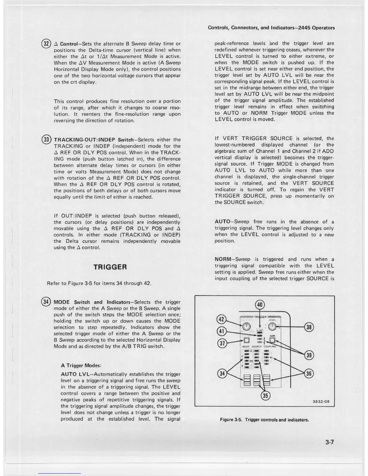
Refer to Figure 3-5 for items 34 through 42.
peak-reference levels and the trigger level are
redefined whenever triggering ceases, whenever the
LEVEL control is turned to either extreme, or
when the MODE switch is pushed up. If the
LEVEL control is set near either end position, the
trigger level set by AUTO LVL will be near the
corresponding signal peak. If the LEVEL control is
set in the midrange between either end, the trigger
level set by AUTO LVL will be near the midpoint
of the trigger signal amplitude. The established
trigger level remains in effect when switching
to AUTO or NORM Trigger MODE unless the
LEVEL control is moved.
If VERT TRIGGER SOURCE is selected, the
lowest-numbered displayed channel (or the
algebraic sum of Channel 1 and Channel 2 if ADD
vertical display is selected) becomes the trigger-
signal source. If Trigger MODE is changed from
AUTO LVL to AUTO while more than one
channel is displayed, the single-channel trigger
source is retained, and the VERT SOURCE
indicator is turned off. To regain the VERT
TRIGGER SOURCE, press up momentarily on
the SOURCE switch.
AUTO—Sweep free runs in the absence of a
triggering signal. The triggering level changes only
when the LEVEL control is adjusted to a new
position.
NORM—Sweep is triggered and runs when a
triggering signal compatible with the LEVEL
setting is applied. Sweep free runs either when the
input coupling of the selected trigger SOURCE is
(34) MODE Switch and Indicators—Selects the trigger
mode of either the A Sweep or the B Sweep. A single
push of the switch steps the MODE selection once;
holding the switch up or down causes the MODE
selection to step repeatedly. Indicators show the
selected trigger mode of either the A Sweep or the
B Sweep according to the selected Horizontal Display
Mode and as directed by the A/B TRIG switch.
A Trigger Modes:
AUTO LVL—Automatically establishes the trigger
level on a triggering signal and free runs the sweep
in the absence of a triggering signal. The LEVEL
control covers a range between the positive and
negative peaks of repetitive triggering signals. If
the triggering signal amplitude changes, the trigger
level does not change unless a trigger is no longer
produced at the established level. The signal
3-7
Figure 3-5. Trigger controls and indicators.

 Loading...


