Controls, Connectors, and Indicators—2445 Operators
READOUT DISPLAY
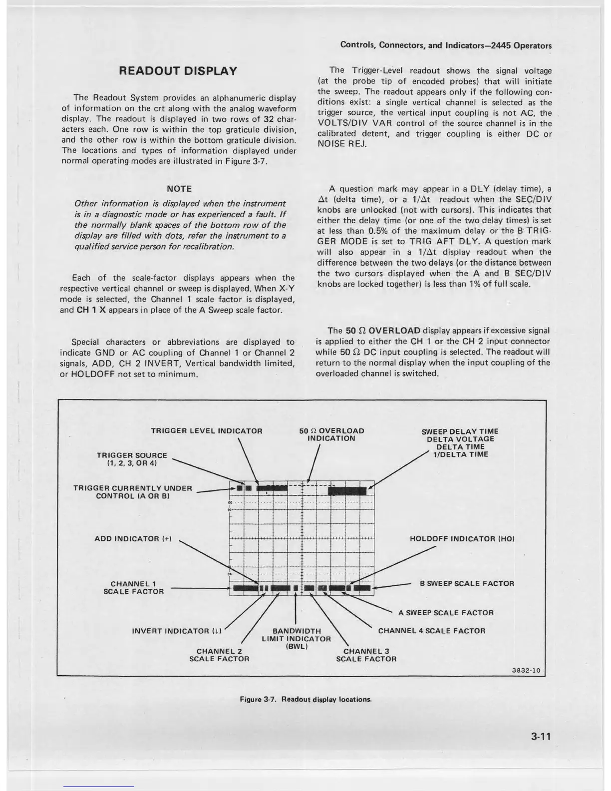
The Readout System provides an alphanumeric display
of information on the crt along with the analog waveform
display. The readout is displayed in two rows of 32 char
acters each. One row is within the top graticule division,
and the other row is within the bottom graticule division.
The locations and types of information displayed under
normal operating modes are illustrated in Figure 3-7.
NOTE
Other information is displayed when the instrument
is in a diagnostic mode or has experienced a fault. If
the normally blank spaces of the bottom row o f the
display are filled with dots, refer the instrument to a
qualified service person for recalibration.
Each of the scale-factor displays appears when the
respective vertical channel or sweep is displayed. When X-Y
mode is selected, the Channel 1 scale factor is displayed,
and CH 1 X appears in place of the A Sweep scale factor.
Special characters or abbreviations are displayed to
indicate GND or AC coupling of Channel 1 or Channel 2
signals, ADD, CH 2 INVERT, Vertical bandwidth limited,
or HOLDOFF not set to minimum.
The Trigger-Level readout shows the signal voltage
(at the probe tip of encoded probes) that will initiate
the sweep. The readout appears only if the following con
ditions exist: a single vertical channel is selected as the
trigger source, the vertical input coupling is not AC, the
VOLTS/DIV VAR control of the source channel is in the
calibrated detent, and trigger coupling is either DC or
NOISE REJ.
A question mark may appear in a DLY (delay time), a
At (delta time), or a 1/At readout when the SEC/DIV
knobs are unlocked (not with cursors). This indicates that
either the delay time (or one of the two delay times) is set
at less than 0.5% of the maximum delay or the B TRIG
GER MODE is set to TRIG AFT DLY. A question mark
will also appear in a 1/At display readout when the
difference between the two delays (or the distance between
the two cursors displayed when the A and B SEC/DIV
knobs are locked together) is less than 1% of full scale.
The 50 fl OVERLOAD display appears if excessive signal
is applied to either the CH 1 or the CH 2 input connector
while 50 £2 DC input coupling is selected. The readout will
return to the normal display when the input coupling of the
overloaded channel is switched.
TRIGGER LEVEL INDICATOR 50 fl OVERLOAD SWEEP DELAY TIME
38 32 -1 0
3-11
Figure 3-7. Readout display locations.

 Loading...


