Specification—2445 Operators
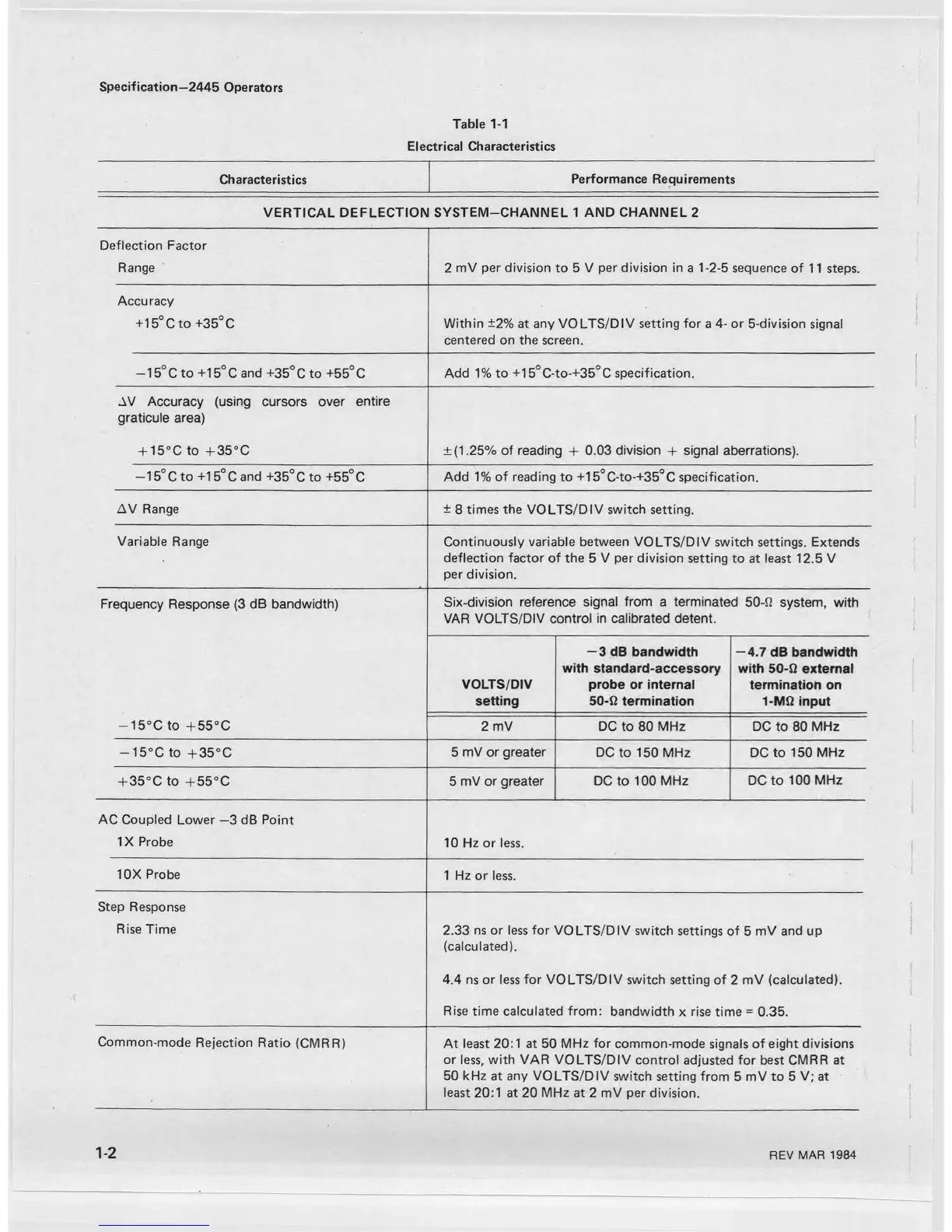
Table 1-1
Characteristics
Electrical Characteristics
Performance Requirements
VERTICAL DEFLECTION SYSTEM-CHANNEL 1 AND CHANNEL 2
Deflection Factor
Range 2 mV per division to 5 V per division in a 1-2-5 sequence of 11 steps.
Accuracy
+15°Cto +35° C
Within ±2% at any VOLTS/DIV setting for a 4- or 5-division signal
centered on the screen.
—15°C to +15°C and +35°Cto +55°C Add 1% to +15°C-to-+35°C specification.
AV Accuracy (using cursors over entire
graticule area)
+ 15°C to +35°C
±(1.25% of reading + 0.03 division + signal aberrations).
—15°C to +15°C and +35°Cto +55°C
Add 1% of reading to +15°C-to-+35°C specification.
AV Range
± 8 times the VOLTS/DIV switch setting.
Variable Range
Continuously variable between VOLTS/DIV switch settings. Extends
deflection factor of the 5 V per division setting to at least 12.5 V
per division.
Frequency Response (3 dB bandwidth)
— 15°C to +55°C
Six-division reference signal from a terminated 50-0 system, with
VAR VOLTS/DIV control in calibrated detent.
VOLTS/DIV
setting
— 3 dB bandwidth
with standard-accessory
probe or internal
50-Q termination
— 4.7 dB bandwidth
with 50-Q external
termination on
1-Mft input
2 mV
DC to 80 MHz
DC to 80 MHz
— 15°C to + 35°C
5 mV or greater
DC to 150 MHz DC to 150 MHz
+ 35°C to + 55°C
5 mV or greater DC to 100 MHz
DC to 100 MHz
AC Coupled Lower —3 dB Point
IX Probe
10 Hz or less.
10X Probe
1 Hz or less.
Step Response
Rise Time
2.33 ns or less for VOLTS/DIV switch settings of 5 mV and up
(calculated).
4.4 ns or less for VOLTS/DIV switch setting of 2 mV (calculated).
Rise time calculated from: bandwidth x rise time = 0.35.
Common-mode Rejection Ratio (CMRR)
At least 20:1 at 50 MHz for common-mode signals of eight divisions
or less, with VAR VOLTS/DIV control adjusted for best CMRR at
50 kHz at any VOLTS/DIV switch setting from 5 mV to 5 V; at
least 20:1 at 20 MHz at 2 mV per division.
1-2
REV MAR 1984

 Loading...


