Basic Applications—2445 Operators
7. Select both ADD and INVERT, release the CH 1
and CH 2 buttons, and slightly readjust the Channel 2
VAR control for maximum cancellation of the undesired
signal component (see Figure 6-3B).
TIME INTERVAL
The built-in Delta Time function greatly simplifies
making various timing measurements. To measure the time
interval between any two points on a waveform (e.g., rise
time, fall times, and periods), use the following procedure.
1. Preset instrument controls and obtain a baseline
trace.
2. Apply the signal to any vertical input connector and
select the VERTICAL MODE switch to display the channel
used.
3. Set the appropriate VOLTS/DIV switch for a con
venient amplitude display of the waveform.
4. Adjust the A TRIGGER LEVEL control to obtain a
stable display.
5. Set the A SEC/DIV switch to a position that con
veniently displays the complete portion of interest of the
waveform.
6. Activate the Delta Time measurement function
by momentarily pressing in the At button. Observe that
two vertical cursors and a At readout appear on the screen.
The Reference cursor is positioned by the A REF OR
DLY POS control, and the Delta cursor is positioned by the
A control. A crt readout in the upper right-hand corner of
the screen displays the time difference between the two
cursors. Changing the SEC/DIV switch position auto
matically changes the readout scale.
7. Position the cursors to the desired points of the
waveform.
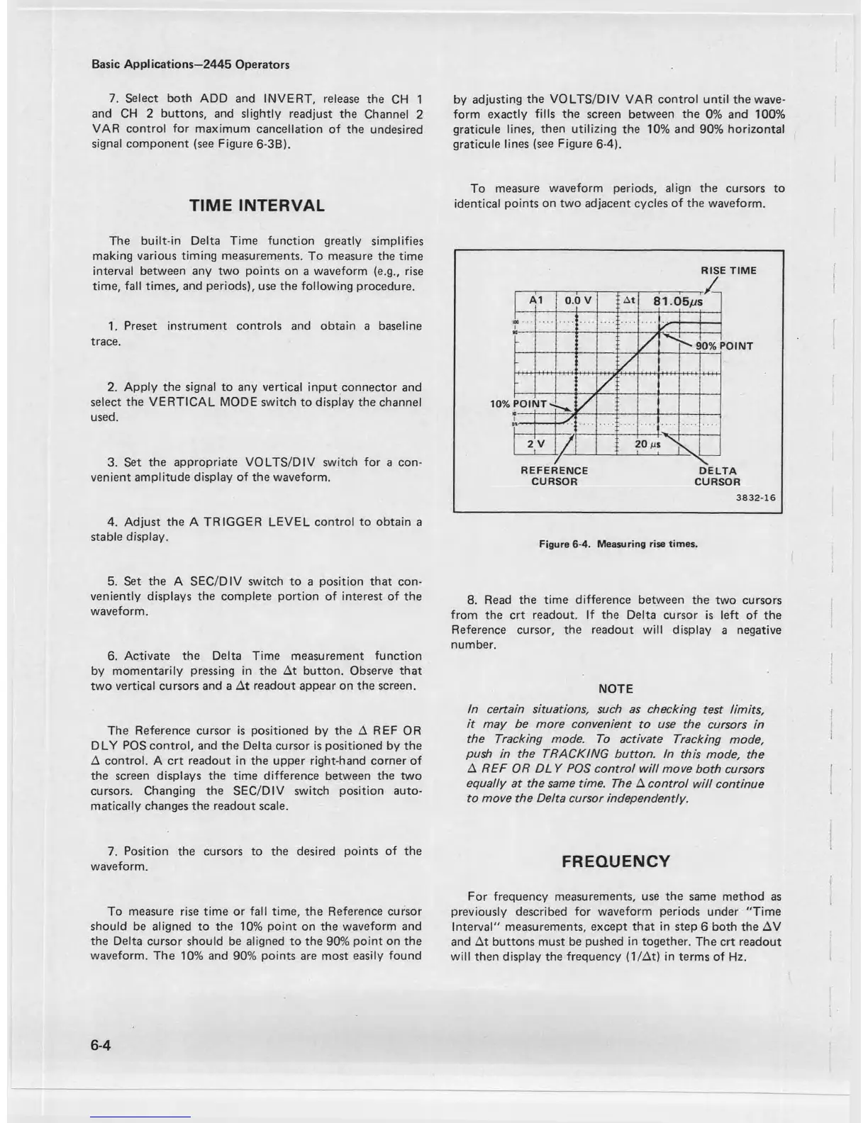
To measure rise time or fall time, the Reference cursor
should be aligned to the 10% point on the waveform and
the Delta cursor should be aligned to the 90% point on the
waveform. The 10% and 90% points are most easily found
by adjusting the VOLTS/DIV VAR control until the wave
form exactly fills the screen between the 0% and 100%
graticule lines, then utilizing the 10% and 90% horizontal
graticule lines (see Figure 6-4).
To measure waveform periods, align the cursors to
identical points on two adjacent cycles of the waveform.
RISE TIME
3 8 3 2 -1 6
Figure 6-4. Measuring rise times.
8. Read the time difference between the two cursors
from the crt readout. If the Delta cursor is left of the
Reference cursor, the readout will display a negative
number.
NOTE
In certain situations, such as checking test limits,
it may be more convenient to use the cursors in
the Tracking mode. To activate Tracking mode,
push in the TRACKING button. In this mode, the
A REF OR DL Y POS control will move both cursors
equally at the same time. The A control will continue
to move the Delta cursor independently.
FREQUENCY
For frequency measurements, use the same method as
previously described for waveform periods under "Time
Interval" measurements, except that in step 6 both the AV
and At buttons must be pushed in together. The crt readout
will then display the frequency (1 /At) in terms of Hz.
6-4

 Loading...


