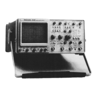
2445 Operators
LIST OF ILLUSTRATIONS
Figure Page
The 2445 Oscilloscope...................................................................................................................... iv
2- 1 Line selector switch, line fuse, and detachable power cord
............................................................
2-2
3- 1 Power and display controls............................................................................................................... 3-1
3-2 Vertical controls and CH 1 OR X and CH 2 connectors.................................................................. 3-2
3-3 Channel 3 and Channel 4 controls and connectors and CALIBRATOR o u tp u t
........................
3-3
3-4 Horizontal and delta measurement controls
...................................................................................
3-4
3-5 Trigger controls and indicators.......................................................................................................... 3-7
3-6 Rear-panel controls and connectors......................................................................................................3-10
3- 7 Readout display locations.....................................................................................................................3-11
4- 1 Graticule measurement markings..................................................................................................... 4-1
5- 1 Probe low-frequency compensation................................................................................................... 5-3
6- 1 Instantaneous dc levels....................................................................................................................... 6-1
6-2 Voltage ratios...................................................................................................................................... 6-2
6-3 Eliminating common-mode signals
..........................................................................................
6-3
6-4 Measuring rise times............................................................................................................................ 6-4
6-5 Time difference between two time-related pulses (cursor m ethod)............................................. 6-5
6-6 Time ratios (duty cycles).................................................................................................................. 6-6
6-7 Phase difference between two time-related signals......................................................................... 6-7
6-8 Small-angle phase difference............................................................................................................. 6-7
6-9 Time difference between two time-related pulses (delayed-sweep method)................................ 6-9
LIST OF TABLES
Table Page
1-1 Electrical Characteristics.................................................................................................................... 1-2
1-2 Environmental Characteristics.......................................................................................................... 1-9
1- 3 Mechanical Characteristics.................................................................................................................. 1-10
2- 1 Voltage, Fuse, and Power-Cord Data................................................................................................ 2-3
A-1 Confidence Test Numbers and Descriptions................................................................................... A-1

 Loading...