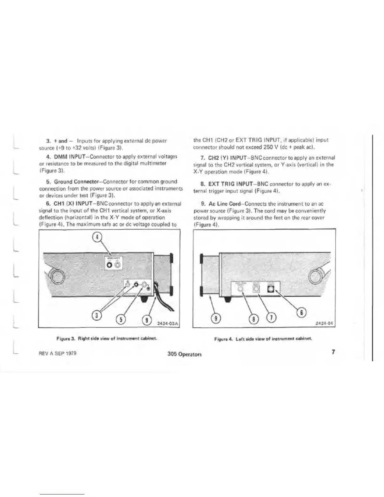
3. + and - Inputs for applying external dc power
source {+9 to +32 volts! {Figure 3).
4. DMM INPUT-Connector to apply external voltages
or resistance to be measured to the digital multimeter
(Figure 3).
5. Ground Connector-Connector for common ground
connection from the power source or associated instruments
or devices under test {Figure 3).
6. CHI (X) INPUT-BNC connector to apply an external
signal to the input of the CHI vertical system, or X-axis
deflection {horizontal) in the X-Y mode of operation
(Figure 4). The maximum safe ac or dc voltage coupled to
the CHI (CH2 or EXT TRIG INPUT, if applicable) input
connector should not exceed 250 V (dc + peak ac).
7. CH2 (Y) INPUT-BNCconnector to apply an external
signal to the CH2 vertical system, or Y-axis (vertical) in the
X-Y operation mode (Figure 4).
8. EXT TRIG INPUT-BNC connector to apply an ex
ternal trigger input signal (Figure 4).
9. Ac Line Cord-Connects the instrument to an ac
power source (Figure 3). The cord may be conveniently
stored by wrapping it around the feet on the rear cover
(Figure 4),
Figure 3. Right tide view of instrument cabinet. Figure 4. Left side view of instrument cabinet.
REV A SEP 1979
305 Operators
7

 Loading...

