DIGITAL MULTIMETER CONTROLS
(FIGURE 9)
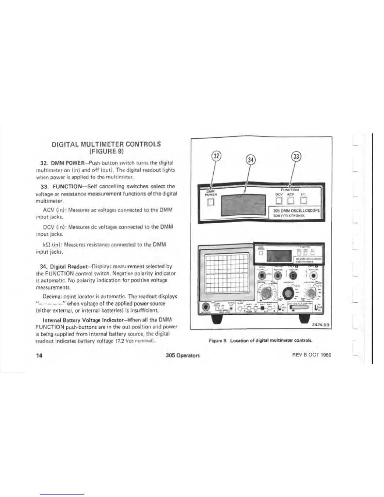
32. DMM POWER-Push-button switch turns the digital
multimeter on (in) and o ff (out). The digital readout lights
when power is applied to the multimeter.
33 FUNCTION—Self cancelling switches select the
voltage or resistance measurement functions of the digital
multimeter.
ACV (in): Measures ac voltages connected to the DMM
input jacks.
DCV (in): Measures dc voltages connected to the DMM
input jacks.
k fi (in): Measures resistance connected to the DMM
input jacks.
34. Digital Readout-Displays measurement selected by
the FUNCTION control switch. Negative polarity indicator
is automatic. No polarity indication for positive voltage
measurements.
Decimal point locator is automatic. The readout displays
"
--------------
" when voltage of the applied power source
(either external, or internal batteries) is insufficient.
Internal Battery Voltage Indicator-When all the DMM
FUNCTION push buttons are in the out position and power
is being supplied from internal battery source, the digital
readout indicates battery voltage (7.2 Vdc nominal)
F.gur* 9. Location of digital multimeter control*.
14
305 Operators
REV B OCT 1980

 Loading...

