......
...............
rnvuu MVjwviiwii
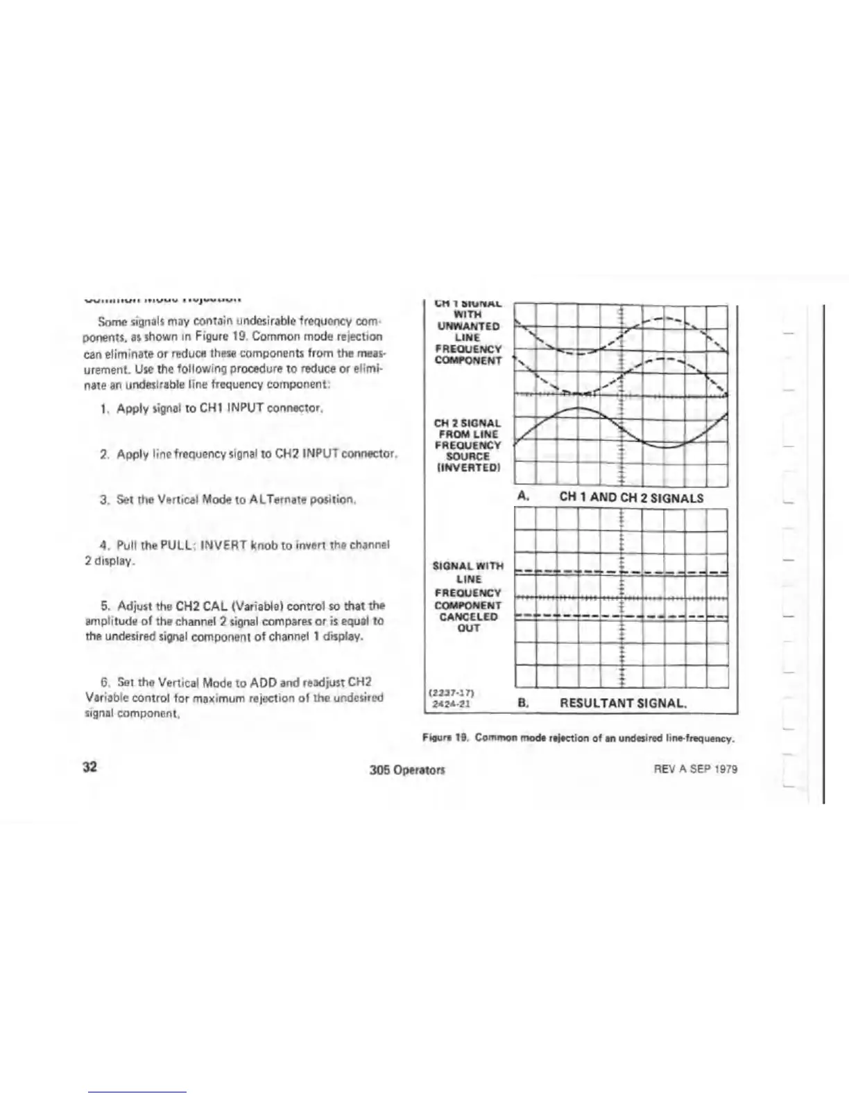
Some signals may contain undesirable frequency com
ponents, as shown in Figure 19. Common mode rejection
can eliminate or reduce these components from the meas
urement. Use the following procedure to reduce or elimi
nate an undesirable line frequency component:
1. Apply signal to CHI INPUT connector.
2. Apply line frequency signal to CH2 INPUT connector.
3. Set the Vertical Mode to ALTernate position.
4. Pull the PULL: INVERT knob to invert the channel
2 display.
5. Adjust the CH2 CAL (Variable) control so that the
amplitude of the channel 2 signal compares or is equal to
the undesired signal component of channel 1 display.
6. Set the Vertical Mode to ADD and readjust CH2
Variable control for maximum rejection ol the undesired
signal component.
CH 1 tklUNAL
WITH
UNWANTED
LINE
FREQUENCY
COMPONENT
CH 2 SIGNAL
FROM LINE
FREQUENCY
SOURCE
(INVERTED!
A. CH 1 AND CH 2 SIGNALS
SIGNAL WITH
LINE
FREQUENCY
COMPONENT
CANCELED
OUT
(2237-17)
2424-21 B. RESULTANT SIGNAL.
Figure 19. Common mod* r*|*ction of an undesired line-frequency.
32
305 Operators
REV A SEP 1979

 Loading...

