tween the signals applied to the CHI and CH2 INPUT con
nectors. This switching between channels occurs at the com
pletion of each sweep. This operating mode is useful when
viewing both input signals at sweep rates of 1 millisecond/
division or faster.
CHOP iChopped): The dual-trace crt display alternates
between the CH1 and CH2 Input signals at a fixed rate of
about 50 kHz. This mode is useful when viewing input
signals at sweep rates of 0.5 millisecond/'division or slower.
ADD: Crt display is the algebraic sum of the signals
applied to the CHI (X) and CH2 (V> INPUT connectors
(CHI plus CH2). When the PULL: INVERT control is
pulled out. the CH2 input signal is inverted providing a
difference display o f signals applied to the CH 1 and CH2
INPUT connectors (CHI minus CH2).
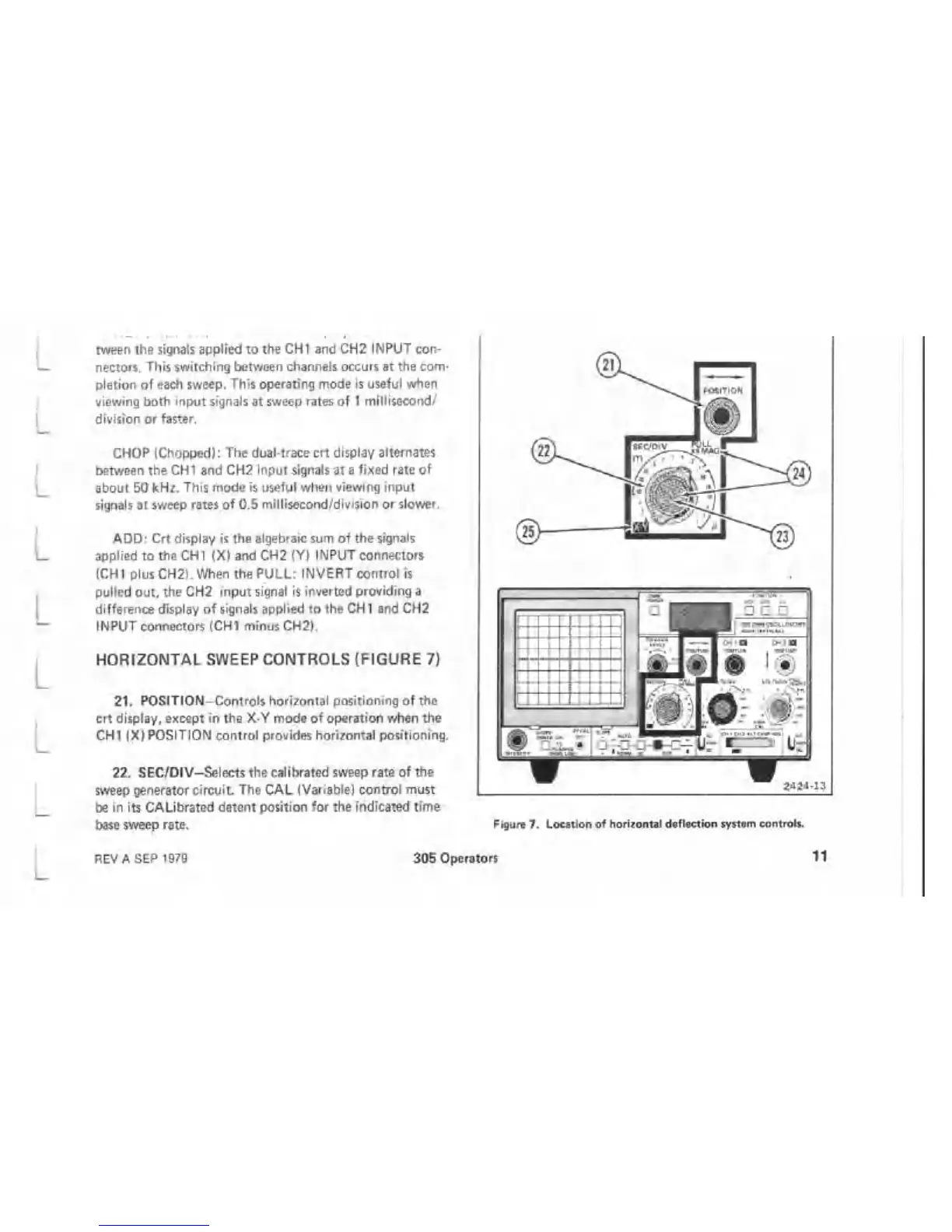
HORIZONTAL SWEEP CONTROLS (FIGURE 7)
21. POSITION-Controls horizontal positioning of the
crt display, except in the X-Y mode of operation when the
CHI (X) POSITION control provides horizontal positioning.
22. SEC/DIV-Selects the calibrated sweep rate of the
sweep generator circuit The CAL (Variable) control must
be in its CALibrated detent position for the indicated time
base sweep rate.
Figure 7. Location of horizontal deflaction system controls.
REV A SEP 1979
305 Operators 11

 Loading...

