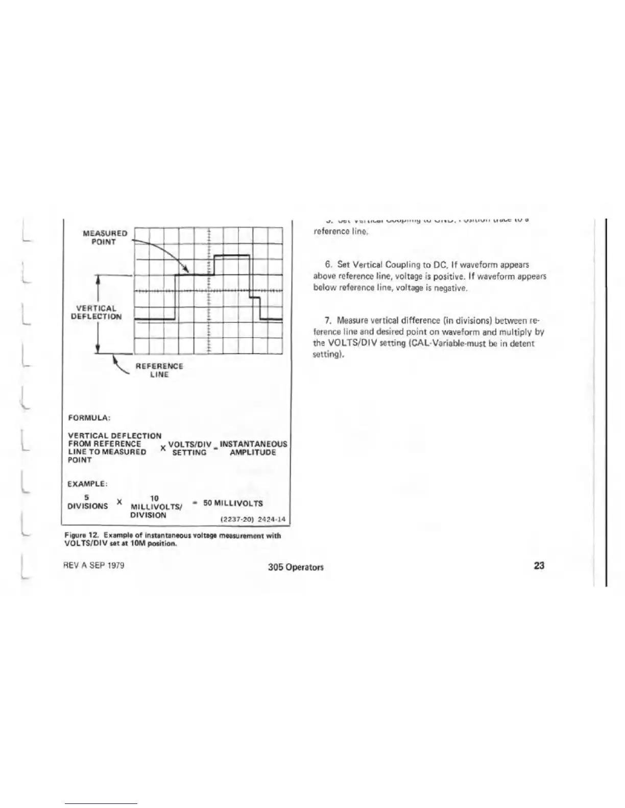
W O 1 (Q IIK iU I w u u p i l l l j l I U W I « U , • O J IH W II M «v* 5 I V »
reference line.
6. Set Vertical Coupling to DC. If waveform appears
above reference line, voltage is positive. If waveform appears
below reference line, voltage is negative.
7. Measure vertical difference (in divisions) between re
ference line and desired point on waveform and multiply by
the VOLTS/DIV setting (CAL-Variable-must be in detent
setting).
FORMULA:
VERTICAL DEFLECTION
FROM REFERENCE x VOLTS/DIV _ INSTANTANEOUS
LINE TO MEASURED
POINT
SETTING AMPLITUDE
EXAMPLE:
DIVISIONS
10
MILLIVOLTS/
DIVISION
- 50 MILLIVOLTS
(2237-20) 2424-14
Figure 12. Example of instantaneous voltage measurement with
VOLTS/DIV sat at 10M position.
REV A SEP 1979
305 Operators
23

 Loading...

