EasyManuals Logo
Home>Tektronix>Test Equipment>465

Tektronix 465 User Manual

Tektronix 465
50 pages
To Next Page IconTo Next Page
To Previous Page IconTo Previous Page
Page #12 background imageLoading...
Page #12 background image
Operating
lnformation-465
5. Re-install
the
cover
and
tighten
the
two
captive
screws.
6.
Before
applying
power
to
the
instrument,
check
that
the
line voltage
selector
switch
and
the
indicating
tab
on
the
Regulating Range
Selector
assembly
are
in
the
correct
position
for
the
desired
nominal
line voltage
and
regulating
range.
This instrument
may
be damaged
if
operated with the
line voltage selector switch or the Regulating Range
Selector assembly set to incorrect positions
for
the
line voltage applied.
The
465
is
designed
to
be used
with
a three-wire AC
power
system.
If
a
three-to
two-wire
adapter
is
used
to
connect
this
instrument
to
a
two-wire
AC
power
system,
be
sure
to
connect
the
ground
lead
of
the
adapter
to
earth
(ground).
Failure
to
complete
the
ground
system
may
allow
the
chassis
of
this
instrument
to
be elevated above
ground
potential
and
pose a
shock
hazard.
The
feet
on
the
rear panel
provide
a
convenient
cord
wrap
to
store
the
power
cord
when
not
in
use.
CONTROLS
AND
CONNECTORS
General
The
major
controls
and
connectors
for
operation
of
the
465 are
located
on
the
front
panel
of
the
instrument.
A
few
auxiliary
functions
are
provided
on
the
rear
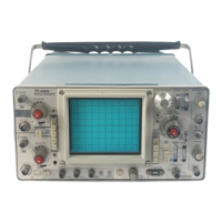
panel. Fig. 2-2
shows
the
front
and
rear
panels
of
the
465.
A
brief
description
of
each
control
and
connector
is
given
here.
More
detailed
operating
information
is
given in
the
465
Oscilloscope
Operators
Handbook.
Cathode-Ray Tube
(CRT)
and
Display
BEAM FIND
INTENSITY
FOCUS
SCALE ILLUM
2-2
Compresses
the
display
to
within
the
graticule
area,
independently
of
display
position
or
applied
signals.
Controls
brightness
of
the
display.
Provides
adjustment
for
optimum
display
definition.
Controls
graticule
brightness.
ASTIG
Screwdriver
adjustment
used
in
conjunction
with
the
FOCUS
control
to
obtain
a well-defined
display.
Does
not
require readjust-
ment
in
normal
use.
TRACE
ROTATION
Screwdriver
adjustment
to
align
the
trace
with
the
horizontal
graticule
lines.
Vertical Deflection System (Channel 1 & Channel
2)
POSITION
CH
1 OR X
CH
2
ORY
GAIN (Side Panel)
VOLTS/DIV
VAR
UNCAL
Input
Coupling
(AC-GND-DC)
Controls
the
vertical
position
of
the
trace.
In
the
X-Y
mode
of
opera-
tion,
the
CH
2
control
positions on
the
Y-axis (vertically)
and
the
Hori-
zontal
POSITION
control
positions
on
the
X-axis
(horizontally).
Input
connector
for
Channel 1 de-
flection
signals
or
X-axis
deflection
in
the
X-Y
mode
of
operation.
Input
connector
for
Channel 2 de-
flection
signals
or
Y-axis deflection
in
the
X-Y
mode
of
operation.
Screwdriver
adjustment
to
set
the
gain
of
the
Vertical
Preamp.
Selects vertical
deflection
factor
in
a 1-2-5
sequence
(VAR
control
must
be in
the
calibrated
detent
for
the
indicated
deflection
factor).
Provides
continuously
variable un-
ca
Ii
brated
deflection
factors
between
the
calibrated
settings
of
the
VOL
TS/DIV
switch.
Light
indicates
that
the
VAR con-
trol
is
not
in
the
calibrated
position.
Selects
the
method
of
coupling
signal
to
the
input
of
the
Vertical
Amplifier.
AC: Signal
is
capacitively
coupled
to
the
Vertical Amplifier. DC
component
of
signal
is
blocked.
Low-frequency
limit
(lower
-3
dB
point)
is
about
10
hertz.
GND:
Input
signal
is
removed
and
the
input
circuit
is
grounded.
Does
not
ground
the
input
signal.
®I
f
C

Table of Contents

Questions and Answers:

Question and Answer IconNeed help?

Do you have a question about the Tektronix 465 and is the answer not in the manual?

Tektronix 465 Specifications

General IconGeneral
BrandTektronix
Model465
CategoryTest Equipment
LanguageEnglish

Related product manuals