Circuit
Description-465
......-----,
High
Voltage
INTENSITY
R1460
Sweep
S1150
ITIME/DIVI
',
$400
',
IBE~MI
,
FIND
'
\ :
Unblanking ....,----4.,___.,_-ll-i
Gate
Chopped
Blanking
TIME/DIV
S1150
C1471
R1468 R1469
Multiplier
U1432
FOCUS
TRACE
/\-----------1---9<
ROTATION
CRT
V1440
R1440
R 1430
;4--+--
- - -
DC
Restorer
C1487, C1488,
CR1487,
CR1488,
R1486
-1--~iASTIGI
R1445
I----+--
- -
--
High Voltage
Oscillator
01418,
T1420
Cathode
Supply
CR1421
C1424
R1453
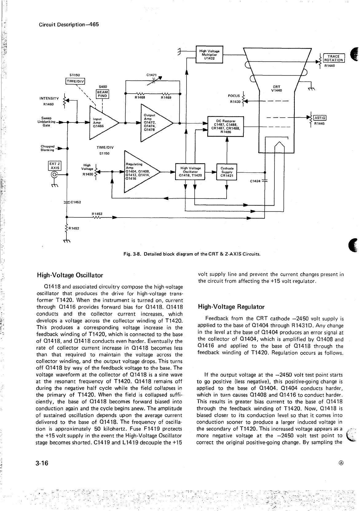
Fig. 3-8. Detailed block diagram
of
the
CRT
& 2-AXIS Circuits.
High-Voltage Oscillator
01418
and associated circuitry compose
the
high-voltage
oscillator
that
produces
the
drive for high-voltage trans-
former
T1420.
When
the
instrument
is
turned on, current
through
01416
provides forward bias for
01418.
01418
conducts and
the
collector
current
increases, which
develops a voltage across
the
collector winding of T1420.
This produces a corresponding voltage increase
in
the
feedback winding of
T1420,
which
is
connected
to
the base
of
01418,
and
01418
conducts even harder. Eventually
the
rate of collector
current
increase in
01418
becomes
less
than
that
required
to
maintain
the
voltage across
the
collector winding, and
the
output
voltage drops. This turns
off
01418
by way
of
the
feedback voltage
to
the
base. The
voltage waveform
at
the
collector
of
01418
is
a sine wave
at
the resonant frequency of
T1420.
01418
remains off
during
the
negative half cycle while
the
field collapses
in
the
primary
of
T1420.
When
the
field
is
collapsed suffi-
ciently, the base of
01418
becomes forward biased into
conduction again and
the
cycle begins anew. The amplitude
of
sustained oscillation depends upon
the
average current
delivered
to
the
base
of
01418.
The frequency of oscilla-
tion
is
approximately
50
kilohertz. Fuse F
1419
protects
the
+15 volt supply
in
the
event
the
High-Voltage Oscillator
stage becomes shorted. C1419 and L
1419
decouple the +15
3-16
volt supply line and prevent
the
current
changes present
in
the
circuit from affecting
the
+15 volt regulator.
High-Voltage Regulator
Feedback from the CRT
cathode
-2450
volt supply
is
applied
to
the
base of
01404
through R1431D. Any change
in
the
level
at
the
base
of
01404
produces
an
error signal
at
the
collector
of
01404,
which
is
amplified by
01408
and
01416
and applied
to
the
base of
01418
through the
feedback winding of T1420. Regulation occurs
as
follows.
If
the
output
voltage
at
the
-2450
volt test point starts
to
go
positive (less negative), th
is
positive-going change
is
applied
to
the base of
01404.
01404
conducts harder,
which
in
turn causes
01408
and
01416
to
conduct
harder.
This results
in
greater bias
current
to
the
base of
01418
through
the
feedback winding
of
T1420.
Now,
01418
is
biased closer to its
conduction
level so
that
it comes into
conduction sooner to produce a larger induced voltage
in
the
secondary of T1420. This increased voltage appears
as
a
more negative voltage
at
the
-2450
volt test point
to
correct
the
original positive-going change.
By
sampling the
®
f
C

 Loading...


