the junction
of
CR315-CR317
is
connected
to
+5 volts
through R361. The Channel 1 Diode Gate blocks the
Channel 1 signal and
the
Channel 2 Diode Gate allows the
Channel 2 signal
to
pass
to
the
Delay Line Driver stage.
Switching Multivibrator
Alternate Trace Display.
In
this mode of
operation,
the
Switching Multivibrator operates as a bistable multivibrator.
When the ALT
pushbutton
is
pressed,
-8
volts
is
applied
to
the
emitter of Alternate Trace Switching Amplifier stage
0352
by
the
VERT MODE switch.
0352
is
forward biased
to
supply
current
to
the
"on"
Switching-Multivibrator
transistor through R352
and
CR368
or CR378. For
example,
if
0374
is
conducting,
current
is
supplied
to
0374
through R352 and CR378. The
current
flow through
collector resistor R371 drops
the
CR305-CR307
cathode
level
negative so
that
the
Channel 1 Diode Gate
is
blocked
as
for Channel 2 Only Operation. The signal passes through
the Channel 2 Diode Gate
to
the
Delay-Line Driver stage.
The alternate trace sync pulse
is
applied
to
the
base of
0352
through C351
at
the
end of each sweep. This
Signal in from
Channel 1 Vertical
Preamp
Signal
in
from
Channel 2 Vertical
Preamp
Circuit Description-465
negative-going sync pulse momentarily interrupts the
current
through
0352
and
both
0364
and
0374
are turned
off. When
0352
turns on again after
the
alternate trace
sync pulse, the charge on C368 determines whether
0364
or
0374
conducts. For example, when
0374
was con-
ducting, C368 was charged positive on
the
CR378
side
to
the
emitter level
of
0374
and negatively
on
the
CR368 side
toward the negative level
at
the
junction of
CR368
and
CR378. This charge
is
stored while
0352
is
off
and holds
the
emitter
of
0364
more negative
than
the
emitter of
0374.
During
the
time
0364
and
0374
are
turned
off, the
voltages
at
their bases become
approximately
equal. Now,
when
0352
comes back
on,
the
transistor with
the
most
negative emitter conducts first,
the
resulting negative
movement
at
its collector holds
the
other
transistor off.
The conditions described previously are now reversed: now,
the
Channel 2 Diode Gate
is
reverse-biased and
the
Channel
1 signal passes through the Channel 1 Diode Gate.
Chopped
Mode Operation. When
the
CHOP
pushbutton
is
pressed,
the
Switching Multivibrator stage free-runs
at
about
a 250 kHz rate. The emitters
of
0364
and
0374
are
connected
to
-8
volts through R368, R378, and the
primary of transformer
T354.
At
the
time
of turn-on, one
Channel 1 Diode Gate
Channel 2 Diode
Gate
R367
To
Delay-Line
Driver
Reverse-biased
diode
--t>f--
*
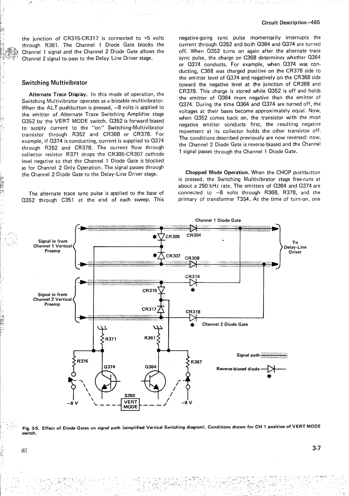
Fig. 3-5.
Effect
of
Diode
Gates
on
signal
path
(simplified Vertical Switching diagram).
Conditions
shown
for
CH 1
position
of
VERT
MODE
switch.
®I
3-7
;,·'
:,_-•
..
..
' - . -.'.·-
..:
:.:
.:·:•-
...
:.:

 Loading...


