Operating basics
Quick Tip
See an applicat
ion example of pulse-width modulation. (See page 94, Motor
Speed Control by Pulse-Width Modulation.)
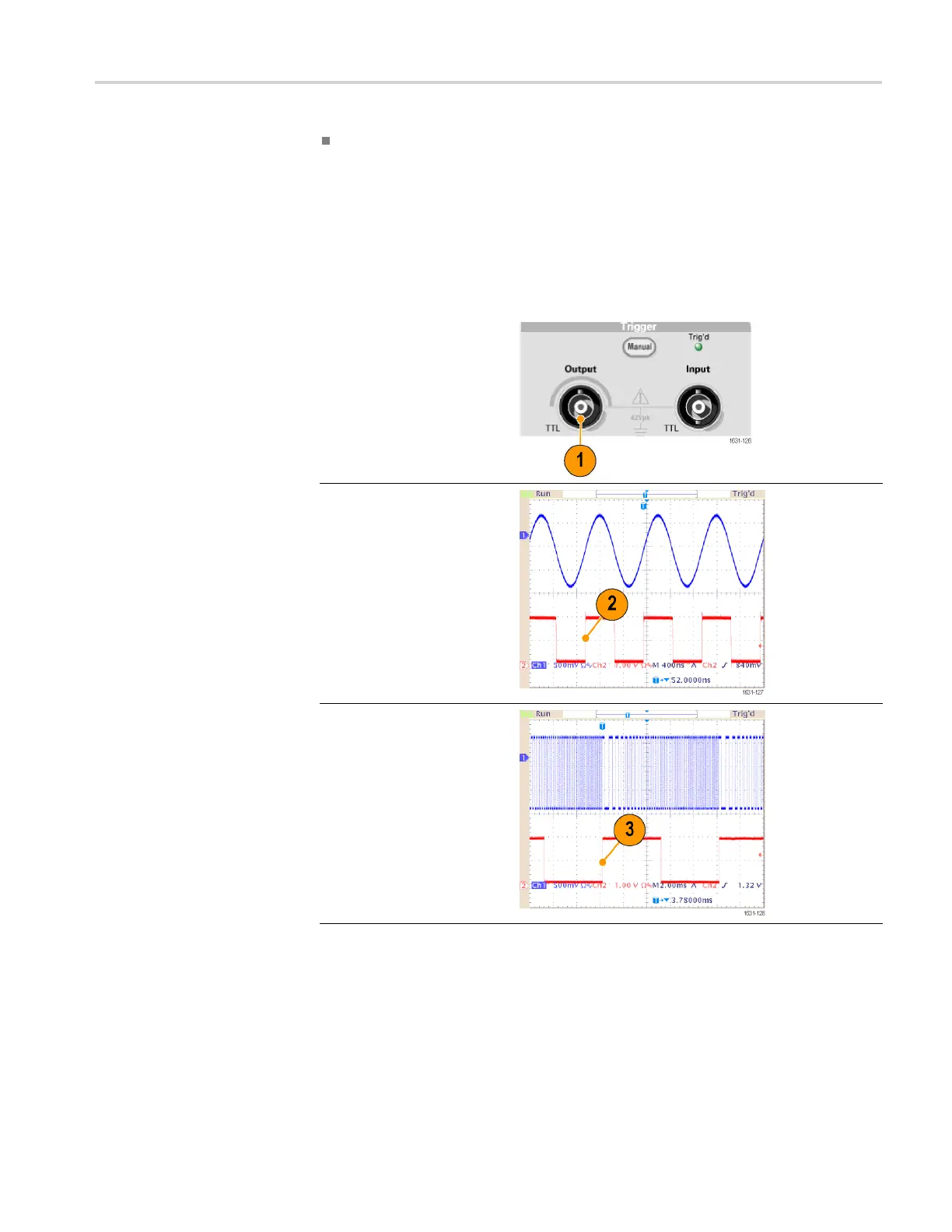
Trigger Out
The Trigger Output signal of the instrument is linked to run mode and function
selected in CH1, if your instrument is a dual-channel model.
1. Connect the
front-panel
Trigger Output connector
and the external trigger
input conn
ector of the
oscilloscopes. The
Trigger Output connector
provides t
he trigger signal
for oscilloscopes.
2. Continuous mode: The
trigger output is a square
waveform
and the ris ing
edge at the start of each
waveform period.
When an o
utput
frequency is higher
than 4.9 MHz, some
restri
ctions are applied.
See the Quick Tips below.
3. Sweep mode: When the
Repea
t or Trigger sweep
mode and internal trigger
source are selected, the
trigg
er output is a square
waveform and the rising
edge at the start of each
swee
p.
AFG3000 and AFG3000C Series User Manual 63
 Loading...


